imple
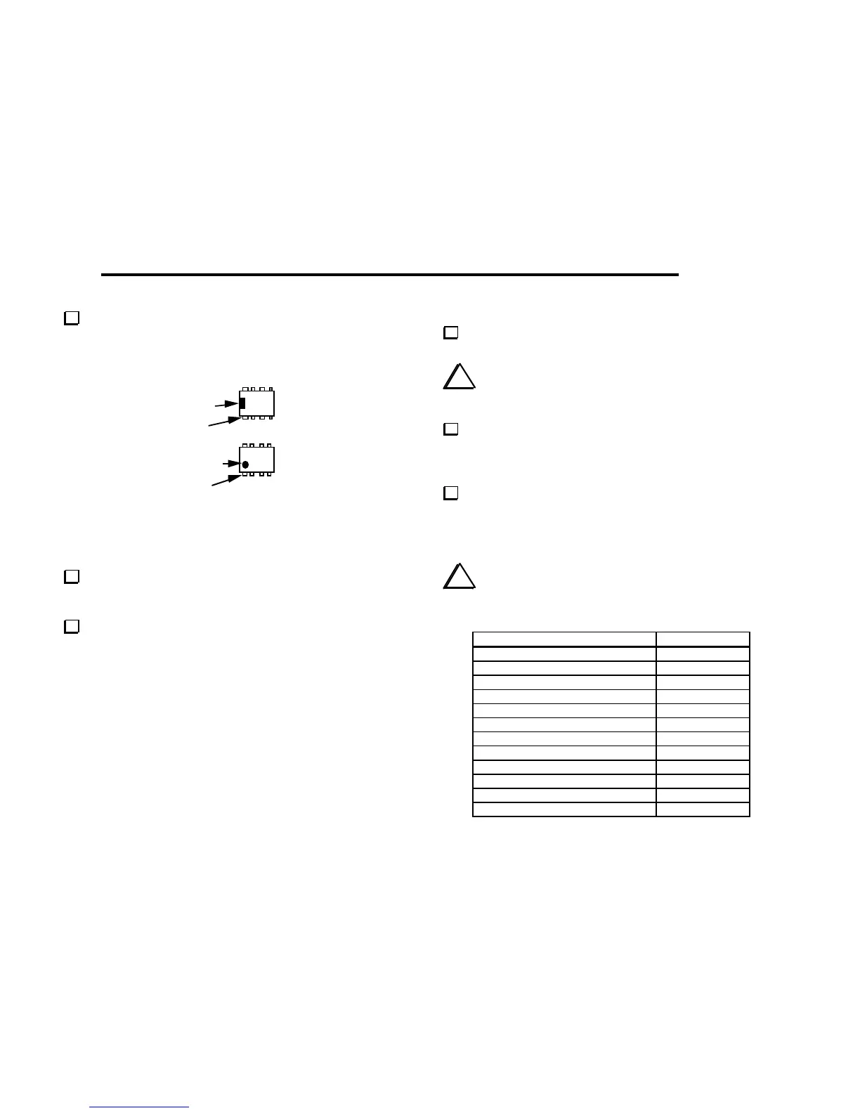
Figure 4-7
Note: IC pins are counted by going around the IC counter-
clockwise from pin 1.
Examine U1 closely. If any pins are bent, remove the IC and
straighten them. (To remove U1 from its socket, pry it up gently
on each end using a small flat-blade screwdriver.)
Locate the blank white area near U1. This area is provided for
labeling the Filter board with the two bands covered (e.g. "40, 20").
Use an indelible marker, dry transfers, or an adhesive label.
Uninstalled Components
All component locations on the Filter board should now be filled
except J1 and J2, which are provided for the automatic antenna
tuner (KAT1). The KAT1 option should be installed only after the
basic K1 kit has been completed and tested. At that time, the
jumper you installed between pins 2 and 10 of J2 will be removed.
Visual Inspection
Using the parts placement drawings in Appendix F, re-check
the orientation of the relays (K1, K2, K3) and U1.
i
About 90% of all problems with kits are caused by poorly-
soldered component leads. Such problems can be avoided by doing a
careful inspection of the board, preferably with a magnifying glass.
Examine the bottom of the PC board closely for cold solder
joints, solder bridges, and unsoldered components.
Resistance Checks
Make the measurements listed below, touching the meter's (+)
and (-) leads to the indicated points. Measurements at relay K3
must be made on the bottom side. Relay pins are numbered like ICs,
with pin 1 identified by its round pad. The Filter board schematic
(in Appendix B) may help you troubleshoot any incorrect readings.
i
The symbol > means greater than, and < means less than.
Your DMM may indicate infinite resistance (all digits flashing) for
readings that are listed as "> 100 k." (Do not use an analog VOM.)
Test Points (+, -) Resistance
U1 pin 6, U1 pin 7 230-270 ohms
U1 pin 6, U1 pin 8 230-270 ohms
U1 pin 6, U1 pin 12 230-270 ohms
U1 pin 13, P2 pin 6 90-110 ohms
P1 pin 1, P1 pin 3 > 100 k
P1 pin 2, P1 pin 3 > 100 k
P1 pin 3, P1 pin 4 > 100 k
P1 pin 3, P1 pin 6 > 100 k
P2 pin 1, P2 pin 2 > 100 k
P2 pin 7, P2 pin 8 > 100 k
K3 pin 2, K3 pin 9 < 5 ohms
K3 pin 4, K3 pin 7 < 5 ohms