


R
Robert WilsonAug 20, 2025
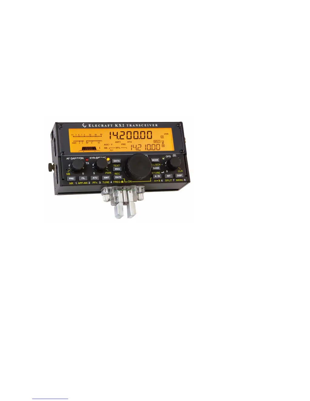
What to do if my ELECRAFT KX2 Transceiver shows HI TEMP warning?
- JJennifer RogersAug 20, 2025
The HI TEMP warning indicates that the PA heat sink temperature has exceeded the safe operating limit. Use DISP to check the power supply voltage, current drain, and PA temperature. Allow the heat sink to cool down, and reduce power if necessary.


