ELECRAFT 21
Inspect the solder side of U1's socket on the top side of the
board. Make sure all pins are soldered, with no cold solder joints.
Using a DMM, check every pair of adjacent pads on U1 on the
top side of the board (pins 1-20 and 21-40). The resistance between
pads should be over 1000 ohms (1 k) in all cases, and may read
infinite on your DMM (often indicated by a flashing display).
i
Before handling U1 in the next step, touch an unpainted,
grounded metal surface.
Straighten the pins of the microcontroller, U1. You can hold
the IC body at the ends as you re-form each row of pins.
Insert U1 into its socket, with the notched end oriented
towards the pin 1 end of the component outline.
Look at both rows of pins on U1 closely. If any pins are bent,
carefully remove the IC by prying at both ends using a small flat-
blade screwdriver. Straighten the pins using long-nose pliers.
Locate the black neoprene LCD spacer (MISC. bag), which is
1/2 x 1/2 square and 3/16" thick (12 x 12 x 5 mm). Remove the
adhesive backing from one side and position the spacer as shown in
Figure 5-7. It must be mounted flat against the PC board, centered
between the two rows of pins on U1's socket.
Spacer
Figure 5-7
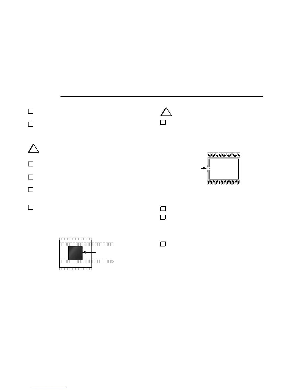
i
Caution: the LCD (DS1) and its pins are fragile.
Remove the LCD from its packing materials, being careful not
to bend the pins. As shown in Figure 5-8, the pin 1 end of the LCD
glass has a very slight bump, along with a break in the black border.
This end will be oriented towards the pin 1 end of DS1's component
outline.
Bump
DS1
112
13
24
Figure 5-8
Remove the adhesive backing from top side of the LCD spacer.
Install the LCD at DS1, oriented as shown above. Make sure
that all 24 pins are inserted into their holes, then press down gently
on the LCD to secure it to the LCD spacer's adhesive surface. The
LCD pins may not extend all the way through the holes. The
surface of the LCD must be parallel to the PC board.
Once the LCD is positioned correctly, solder all pins.