ELECRAFT 25
6. RF Board, Part I
In Part I, the VFO (variable-frequency oscillator) and receiver
sections will be assembled.
Open the bag labeled RF and sort the components into groups.
Observe anti-static precautions when handling transistors and ICs.
T-R Switch
and Transmitter
VFO
Receiver
J6
J8
J7
AF Amp
Figure 6-1
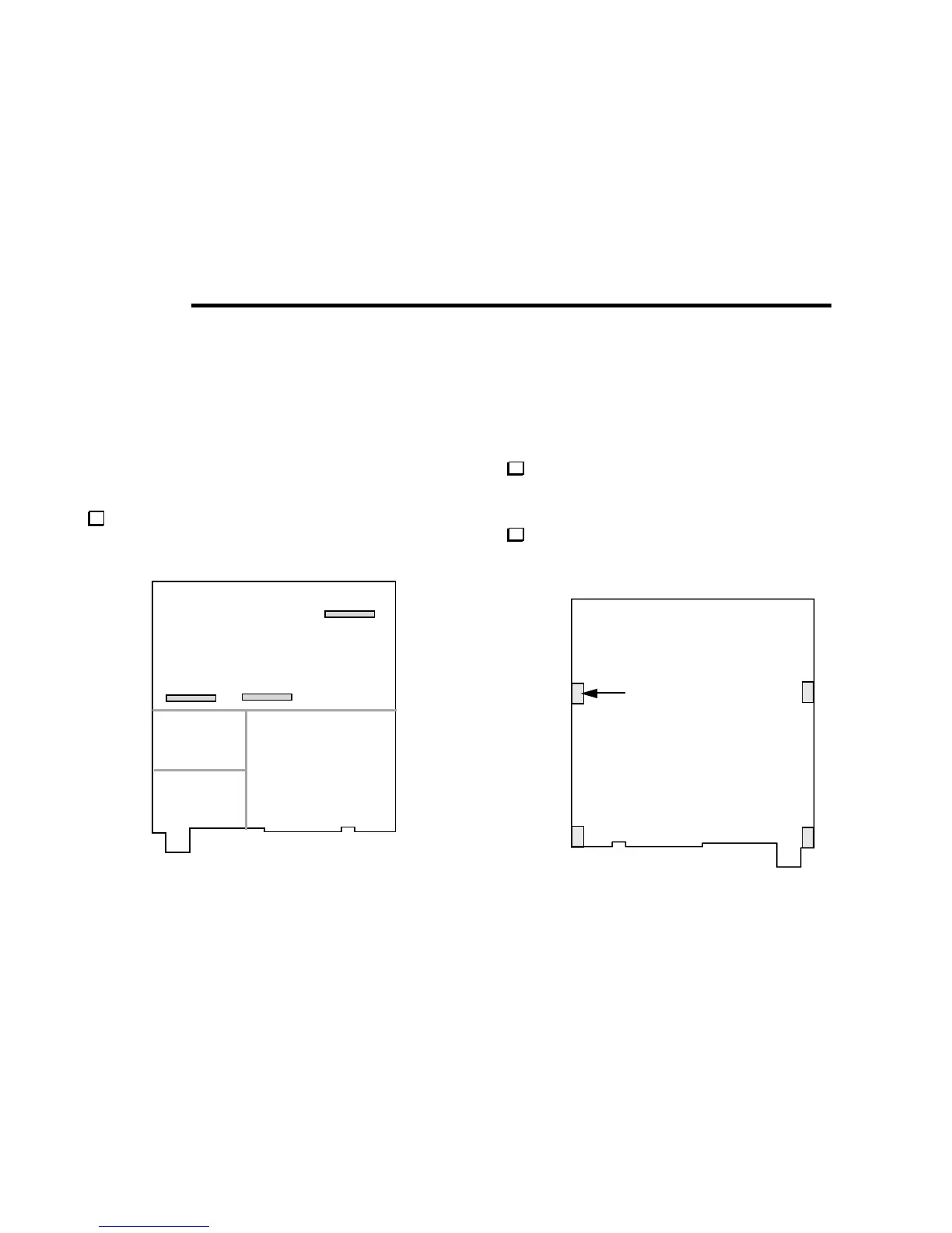
Locate the RF board and orient it as shown in Figure 6-1. This
illustration shows the major areas of the board. Receiver and VFO
circuits occupy the front half; transmitter and T-R switch stages use
the rear half. The Filter board plugs into J6, J7, and J8.
Turn the board over. (Figure 6-2 shows the bottom side.)
Four 2-D fasteners will be attached to the RF board at the indicated
locations to secure it to the chassis panels.