-
Figure 6-6
Install the electrolytic capacitors listed below. They must be
seated as close to the PC board as possible to avoid interfering with
option modules that you may install later. Note: The 10-µF
capacitors are of the low-profile type, so they may be smaller than
the 2.2-µF capacitors.
__ C33, __ C59, and __ C35, 10 µF (see note above)
__ C54, __ C31, and __ C67, 2.2 µF
__ C9, __ C10, and __ C53, 220 µF
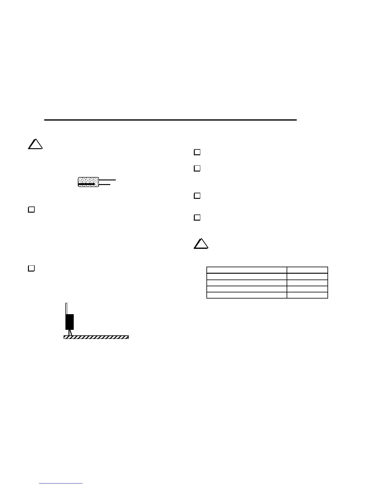
8-volt regulator U5 (LM2930T-8) is a TO-220 package
device with 3 leads (see photo in parts list). Mount U5 vertically at
the back edge of the PC board (Figure 6-7). Only the wide part of
the leads should be above the board. The hole in the tab of U5 will
not be used for mounting, so positioning is not critical.
Figure 6-7
DC Voltage Checks
Set power switch S1 to its OFF position, with the plunger out
(extended toward the back).
Connect a 12 to 14-V DC power supply or battery to J4. If
your power source does not already have a plug that mates with J4,
use the supplied mating plug and prepare a suitable power cable. The
center lead of the plug is positive (+).
Turn on S1. If you see or smell smoke, or a component
feels hot to the touch, disconnect the power source
immediately. Locate the source of trouble before proceeding.
Using your DMM's DC voltage setting, make the DC voltage
checks listed below. The (-) lead of your DMM should be connected
to one of the ground jumpers.
i
Be careful not to short adjacent pins of ICs with the DMM
probe (use only a fine-point probe).
Test Point (+) DC Voltage
P1 pin 15 5.8-6.2
P1 pin 16