ELECRAFT 43
i
TO-220 package transistors Q6 and Q7 look identical, but
are different types. Locate the 2SC1969 (labeled "C1969"), Q7,
and set it aside. The 2SC2166 transistor, Q6 ("C2166"), will be
installed first.
Attach a self-adhesive thermal pad to the PC board on top of
the component outline for Q6. The hole in the thermal pad must
be aligned precisely with Q6's mounting hole on the board.
Prepare the leads of Q6 as shown below, bending them
downwards to match their pads. To avoid stressing the leads, use
smooth bends, rolling them over a small screwdriver blade or
forming them using long-nose pliers.
end, not 90°
Figure 8-1
Secure Q6 to the board using a 4-40 x 3/8" (9.5 mm) pan-head
screw (shiny finish, not black), #4 internal-tooth lock washer, and
4-40 nut. The screw should be inserted from the bottom side (Figure
8-1).
Verify the part number on Q6 (2SC2166 or C2166), then
solder. Trim the pins on the bottom.
Remove the right side panel if it is still attached.
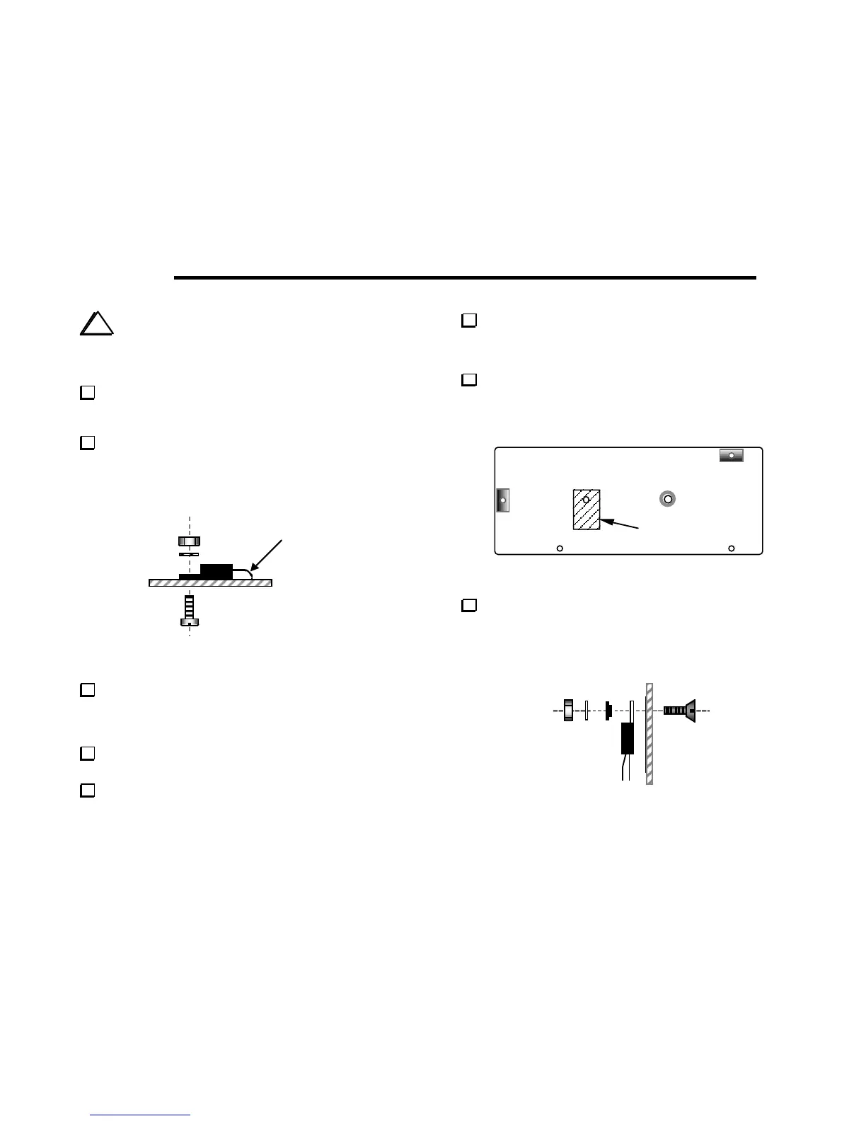
Identify the hole in the right side panel where the thermal
insulator will be placed (Figure 8-2). If the edge of the hole is not
completely smooth, use a large drill bit to de-burr the hole by hand.
Follow with a small amount of light sanding of the indicated area.
Attach a self-adhesive thermal pad to the side panel at the
location shown in Figure 8-2. The hole in the thermal pad must be
aligned precisely with the hole in the panel. The pad must be
straight, not tilted or skewed in either direction.
Thermal insulator
Figure 8-2
Attach Q7 to the right side panel using the hardware shown in
Figure 8-3: a 5/16" (8 mm) x 4-40 flat-head screw, shoulder washer
(black plastic), #4 internal-tooth lock washer, and 4-40 nut. The
small-diameter part of the shoulder washer must be inserted into
the hole in Q7's tab. Do not over-tighten the hardware.
Figure 8-3