1
(RED)
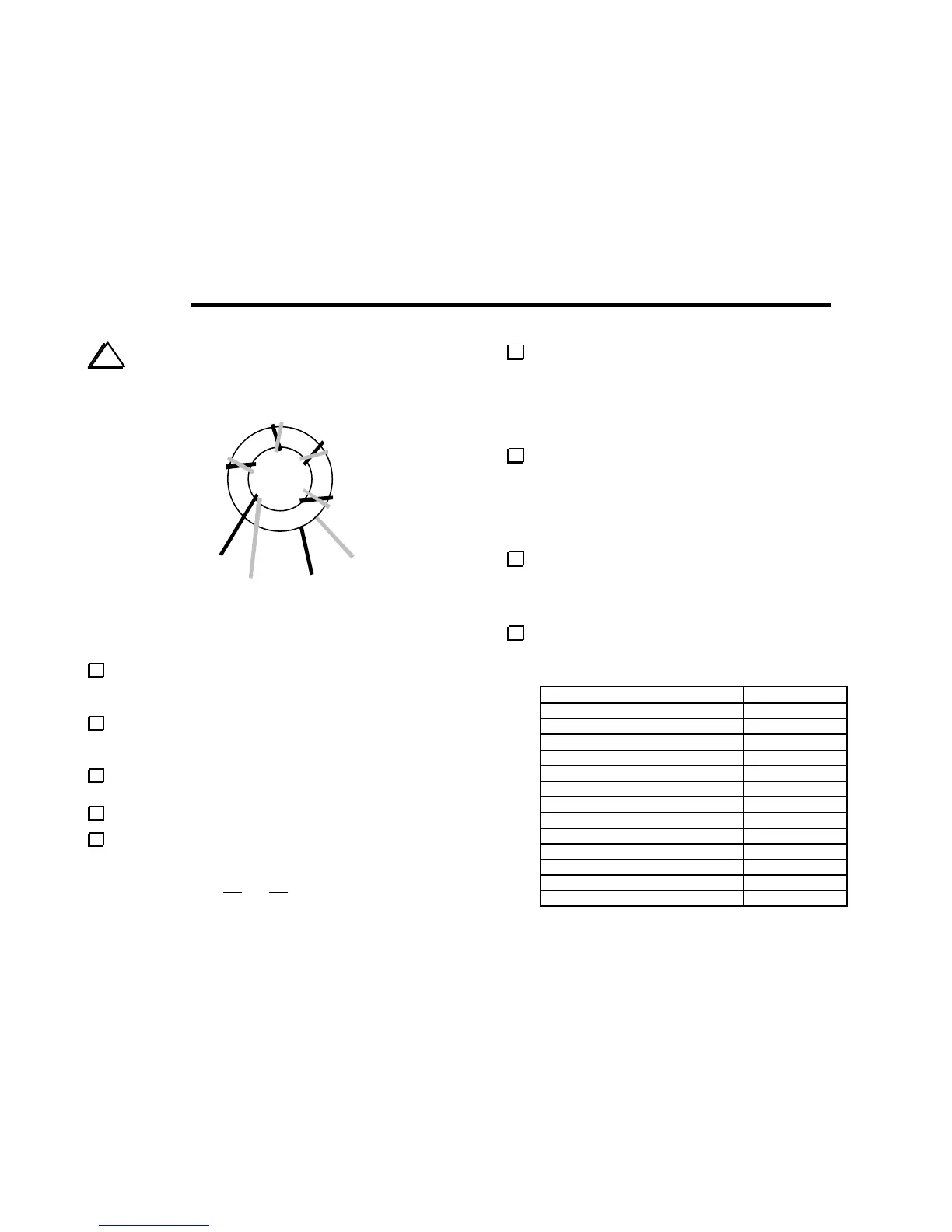
Figure 8-5
Cut two 8" (20 cm) lengths of enamel wire, one red and one
green. Twist the wires together over their entire length. The wires
should cross over each other approximately every 1/2" (1 cm).
Wind the twisted wires onto the 1/2" (12.7 mm) dia. ferrite
core (FT50-43, dark gray), using 5 turns and covering about 85% of
the core. Figure 8-5 shows how the winding should look.
Separate T4’s leads as shown in Figure 8-5. Strip and tin the
leads. Be careful not to let the red and green wires short together.
Install T4 flat against the PC board as indicated by its outline.
Using your DMM on a low resistance scale, measure continuity
between the #1 and #2 pads of T3. If you get a reading over 5
ohms, re-strip the affected lead(s). Similarly, check the 3-4 winding
of T3. Then check T4's 1-3 and 2-4 windings.
If you plan to operate the K1 on 80 meters, and your K1 RF
board is revision D or earlier, you may need to make a minor
modification to the PC board. Please refer to the errata sheet
included with the K1B80 (80-m Band Kit).
Uninstalled Components
Make sure that all component locations on the RF board have
been filled, except for two: J1, which is supplied with the noise
blanker option kit (KNB1), and C78, which may be supplied with
the 80-m band kit for the 2-band Filter board.
Visual Inspection
Examine the bottom (solder side) of the RF board carefully for
unsoldered pins, solder bridges, or cold solder joints.
Resistance Checks
For the following measurements, connect the (-) lead of your
DMM to a ground jumper. When making measurements at J7 and
J8, use a component lead or hookup wire as a probe tip.
Test Points (+) Resistance
J7 pin 1 2.4-3.0 k
J7 pin 4 > 1 k
J7 pin 5 > 100 k
J7 pin 6 5 - 7 k
J7 pin 8 1.5-2.0 k
J8 pin 1 > 100 k
J8 pin 5 90-110 k
J8 pin 7 1.6-1.9 k
U4 pin 7 > 1 k
U8 pin 8 > 100 ohms
U9 pin 7 > 1 k
D9 cathode (banded end) 1.5-2.0 k
D9 anode > 100 ohms