ELECRAFT 7
Board-to-board Connectors
The circuit boards in the K1 plug in together using board-to-board connectors, which eliminates nearly all hand wiring. Gold-plated contacts
are used on these connectors for reliability and corrosion resistance.
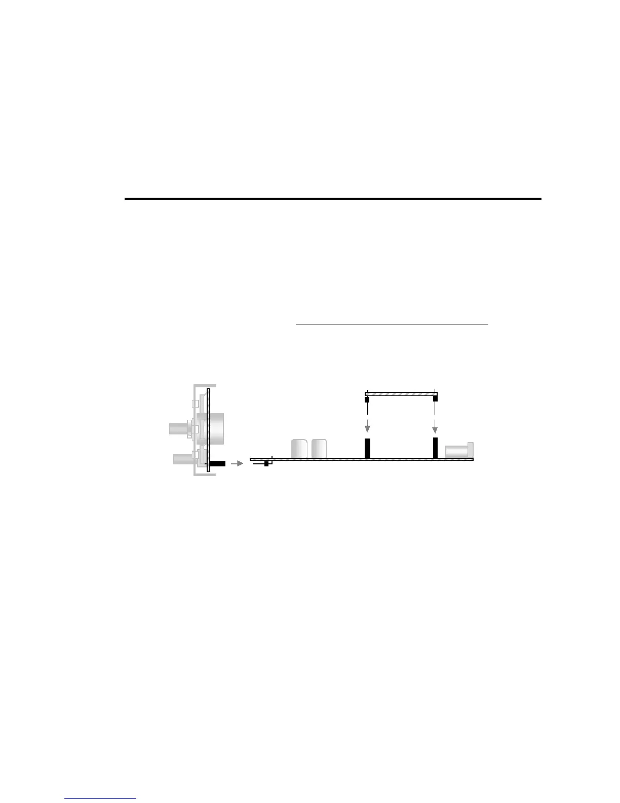
Figure 3-3 shows a side view of the PC boards and board-to-board connectors. As can be seen in the drawing, the Front Panel board has a
connector J1 which mates with right-angle connector P1 on the RF board. The Filter board has three connectors, P1, P2 and P3, which mate
with J6, J7 and J8 on the RF board.
These multi-pin connectors are difficult to remove once soldered in place. Refer to Figure 3-3 during assembly to make sure
you have each connector placed correctly before soldering. If you install a multi-pin connector incorrectly, clip all of the pins at
the body of the device first, remove all of the pins individually, and call us to request a new connector. You may damage pads
and traces by trying to remove such components intact.
J1
8
Figure 3-3
K1-2 (2-band version) and K1-4 (4-band version)
This manual covers all aspects of assembly for the two-band K1 (model K1-2). If you purchased a four-band K1 (model K1-4), you'll use the
KFL1-4 assembly manual during assembly and alignment of the Filter board. You'll find instructions specific to the 4-band module at all
appropriate places in this Owner's manual.