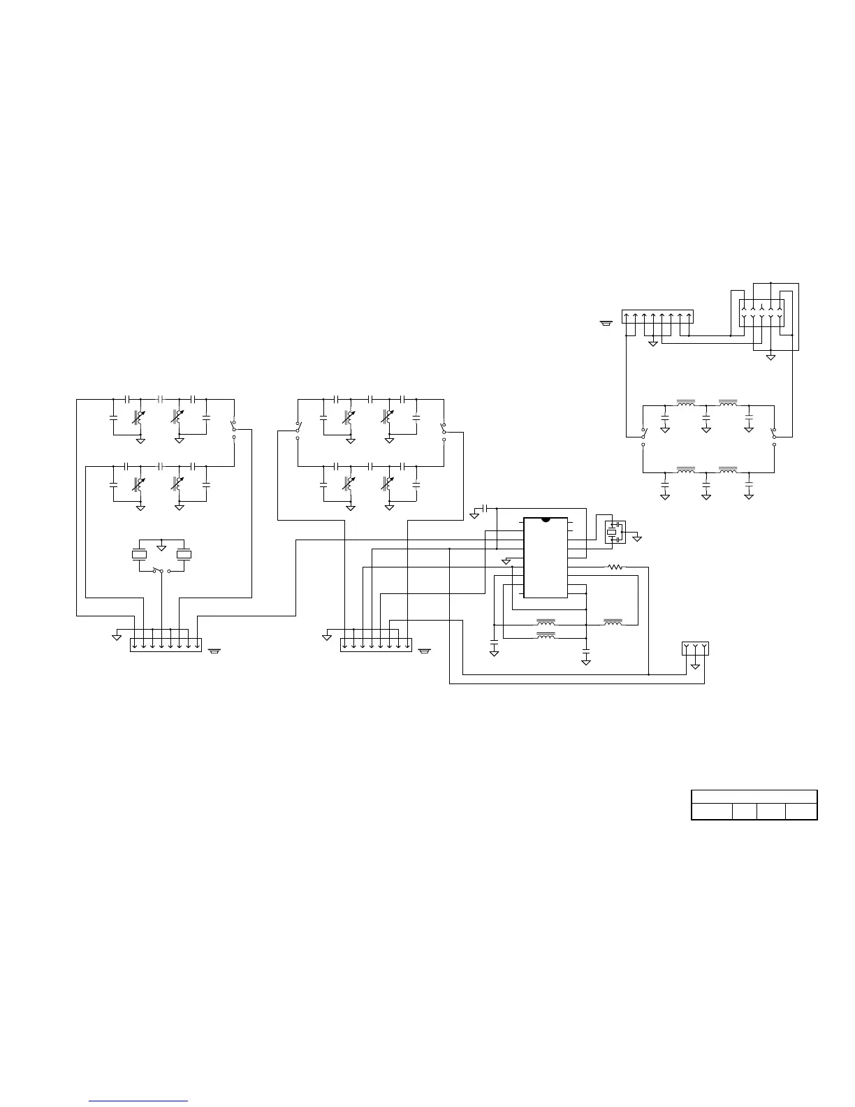
Premix Band-Pass Filters RF Band-Pass Filters
Low-Pass Filters
Appendix B
W. Burdick
PIC16C620A
Elecraft
E.Swartz
/AGC OFF
To RF-J6 To RF-J7
To RF-J8
/AGC OFF
ATTN RY
1 of 1
Band 1
Band 2
Band 1
Band 2
Band 1
Band 2
Band 1 Band 2
PREMIX
RF OUT
RY COM
Rev. Sht.
RF IN
Date
MCLR
OSC1
OSC2
XOSC
.001
.001
C21 C22
C23
L10
RA2
RA3
RA4
VSS
RB0
RB1
RB2
RB3
RA1
RA0
VDD
RB7
RB6
RB5
RB4
C10
K1B
C24 C25
C26
L11 L12
K3B
K3A
C13
C15
C11
C12 C14
C18
C20C16
C17 C19
K2B
K1A
C30
C29
100
K2A
By
L9
K1
K2
10
10
10
11
12
13
14
15
16
17
18
U1
K3
10
C3
C5C1
C4
L1 L2
C8
C6
C7 C9
L3 L4
L5
L6
L7 L8
P1
P2
P3
X1
X2
6A
PA
C2
R1
1
1
1
2
3
4
5
6
7
8
9
1
2
4
3
2
4
3
9
7
8
2
4
3
123 45678 12345678
12345678
9
7
8
9
7
8
Z1
.047
C27
4 MHz
6R/AUX
123
J1
To ATU-P1
10
1
2
3
4
5
6
7
8
9
J2
To ATU-P2
(Note 1)
(Note 1)
Notes:
connected using a jumper (see text).
(See Note 2)
I/O Controller
If the KAT1 is not installed, J2 pins 2 and 10 must be
used as tie points for other circuitry on the PC board.
Pins 5 and 6 of relays are not connected internally, but may be
E
1/5/02
K1 2-Band Filter Board
manual for 4-band Filter baord schematic.
3. K1-K3 are latching relays, and are shown in the RESET position.
2. See Parts List for values of all band-specific components.
1. J1 and J2 are supplied with the KAT1 option (Antenna Tuner).
4. This schematic is for the 2-band Filter board. Refer to KFL1-4