7
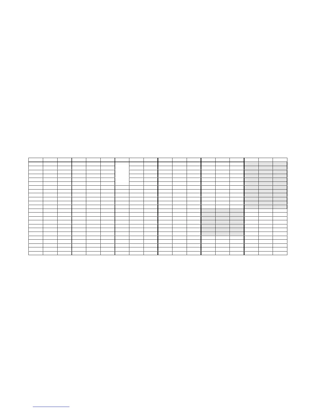
DC Voltage Table
NOTES: Measurements listed for FIL-U1 apply only to the two-band Filter board; for 4-band Filter board voltages, refer to the KFL1-4
manual. Measurements were made with a 50-ohm dummy load connected and a supply voltage of 14 V. In general, your measurements should
be within 10% of the values shown. Pins NOT listed in the table should indicate 0.0 volts DC. Pins marked with (*) are hard to measure
due to noise pickup. Shaded areas show transmit-mode measurements (using TUNE), made with the Filter board removed.
Reference designators are prefixed with the board identifier: “FP” = front panel board, “RF” = RF board, “FIL” = filter board.
Ref. Pin VDC Ref. Pin VDC Ref. Pin VDC Ref. Pin VDC Ref. Pin VDC Ref. Pin VDC
FP-U1 1 6.0 FP-U2 1 1 to 5 3 0.8-1.0 RF-U1 1 1.4 RF-U4 6 6.6 RF-U9 2 6.8
2 1.1 3 6.0 4 6.0 2 1.4 7 13.6 3 6.8
3 6.0 4 6.0 13 5.5 4 4.9 8 6.8 6 6/8
4 1.8 7 6.0 14 6.0 5 4.9 7 13.6
5 6.0 15 < 0.3 6 6.0 RF-U7 1 1.4
6 2.5 FP-U3 5 6.0
FIL-U1
16 < 0.3 7 5.3 2 1.4 RF-Q6 B 1.1
8 5.6 6 6.0 8 6.0 4 4.8 C 13.6
9 3.0 8 6.0 5 4.8 E 0.5
10 3.0 RF-U2 1 * 6 6.0
11 6.0 FP-U5 1, 2, 3 3.0 2 1.4 7 5.3 RF-Q7 B 0.0
13 2.3 5 6.0 4 * 8 6.0 C 13.6
14 2.8 6 4.8 5 * E 0.0
15-17 3.0 7 4.8 6 6.0 RF-U8 1
18 6.0 8 6.0 7 5.4 2
19-22 3.0 8 6.0 4
23 6.0 5
24-30 3.0 RF-U3 1 1.3 6
32 6.0 2* 7
33-39 3.0 3* 8
40 6.0 5 4.0
6 8.0
7 4.0
8 1.3