ELECRAFT 33
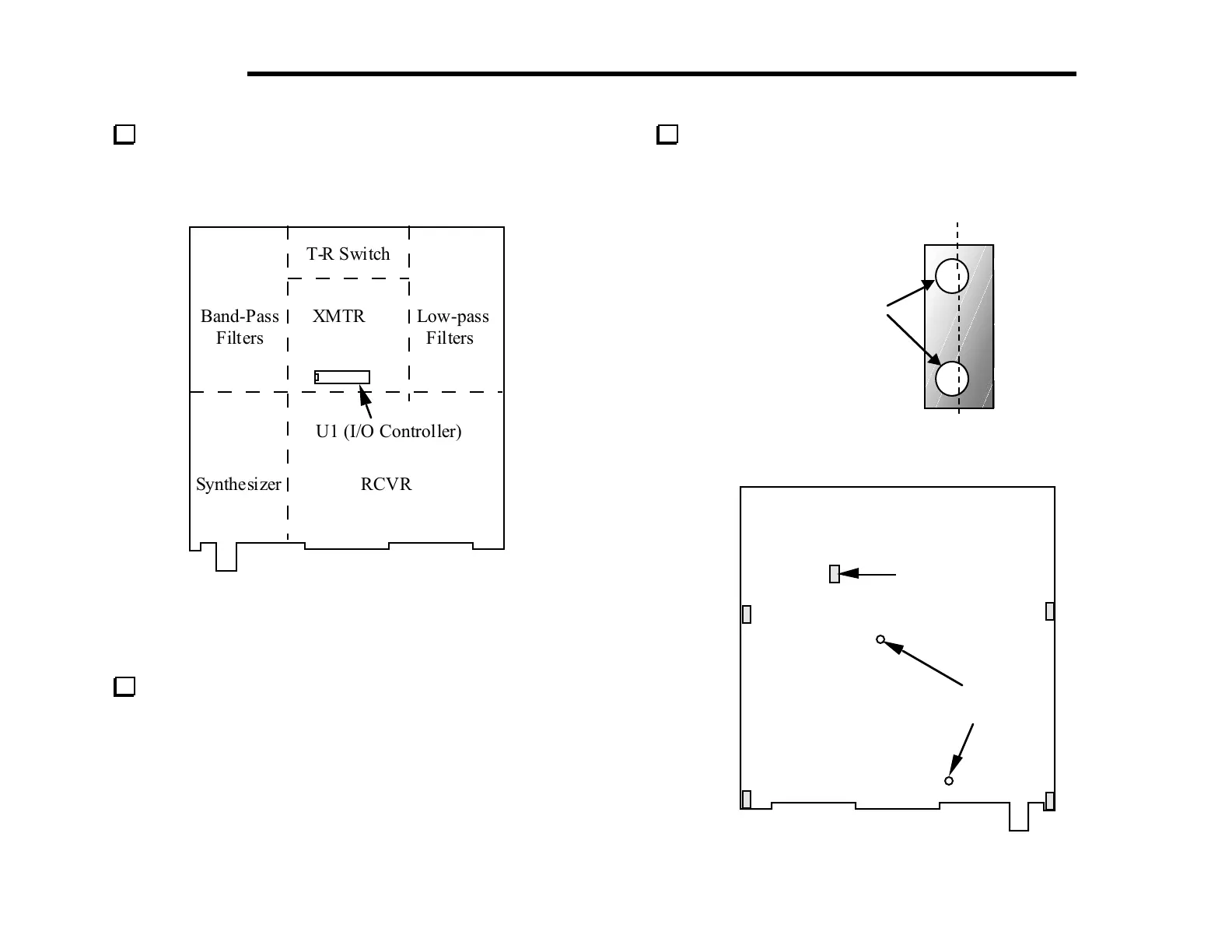
Take a moment to familiarize yourself with the RF board using
Figure 6-1 to identify the major sections. If you flip the board over
you’ll see that there are a few components on the bottom of the
board, primarily in the transmitter section.
T-R Switch
Band-Pass XMTR Low-pass
Filters Filters
U1 (I/O Controller)
Synthesizer RCVR
Figure 6-1
Assembly, Part I
Locate a 2-D fastener and hold it vertically as shown in Figure
6-2. Looking at a side with two holes, note that the holes are offset
from the center. When you install the fasteners in the following
step, be sure to position them so that the holes in the fastener are
shifted in the same direction as the holes in the PC board outlines
on the bottom of the board.
Turn the board over and install 2-D fasteners at five locations
on the bottom of the RF board as shown in Figure 6-3. Secure each
fastener from the top side of the board using two chassis screws
(black, 3/16" [4.7 mm]) and two #4 lock washers.
Holes offset
from center
Figure 6-2
(Bottom of board)
1/4"
Standoffs
2-D Fasteners
(5)
Figure 6-3