ELECRAFT 35
Install the self-resetting fuse, F1, near D10. F1 is yellow and
looks like a square-bodied capacitor. One side is labeled "G300".
Install the key jack, J1, at the back-left corner of the board.
Before soldering, make sure that the jack is aligned with its PC
board outline.
Install the headphone jack, J2, on the small board extension
near the front left corner. The pins on J2 are not very long, so
they will be nearly flush with the bottom of the board. Solder the
pin closest to the front edge first (ground), then verify that the
jack is seated flat on its plastic nubs before soldering the remaining
pins.
Install the power switch, S1, at the right front corner. (S1's
key cap will be installed later.)
Install the DC input jack, J3, at the back right corner. The 3
leads on the jack must be lined up with the slot-shaped holes in the
component outline. If the holes are a tight fit, press firmly until
the connector snaps into position.
Install the antenna jack, J4 (BNC), just to the left of J3.
Install the following components near U1 (at the middle of
the board). You may need to confirm the part number of U2
(78L06), since it is easy to confuse it with U8 (78L05). Use a
magnifying glass if necessary.
__ U2 (78L06) __ C139, 0.1 (104)
__ C140, .001 (102) __ R64, 100 (BRN-BLK-BRN)
Install the ceramic resonator, Z5, near U1. (The ceramic
resonator looks like a capacitor with three pins.)
Install R65 (10 k, BRN-BLK-ORG) on the bottom of the
board, near U1.
Install D8 and D18 (1N4148), on the bottom of the board,
toward the right edge. Make sure the banded end of each diode is
aligned with the band on its component outline.
i
In the steps that follow you’ll install the connectors that
mate with the control and Front Panel boards. These connectors
must be installed properly to ensure reliable mechanical connection.
They are very difficult to remove once installed, so follow all
instructions carefully. Review Figure 3-3 (page 8) for correct
placement.
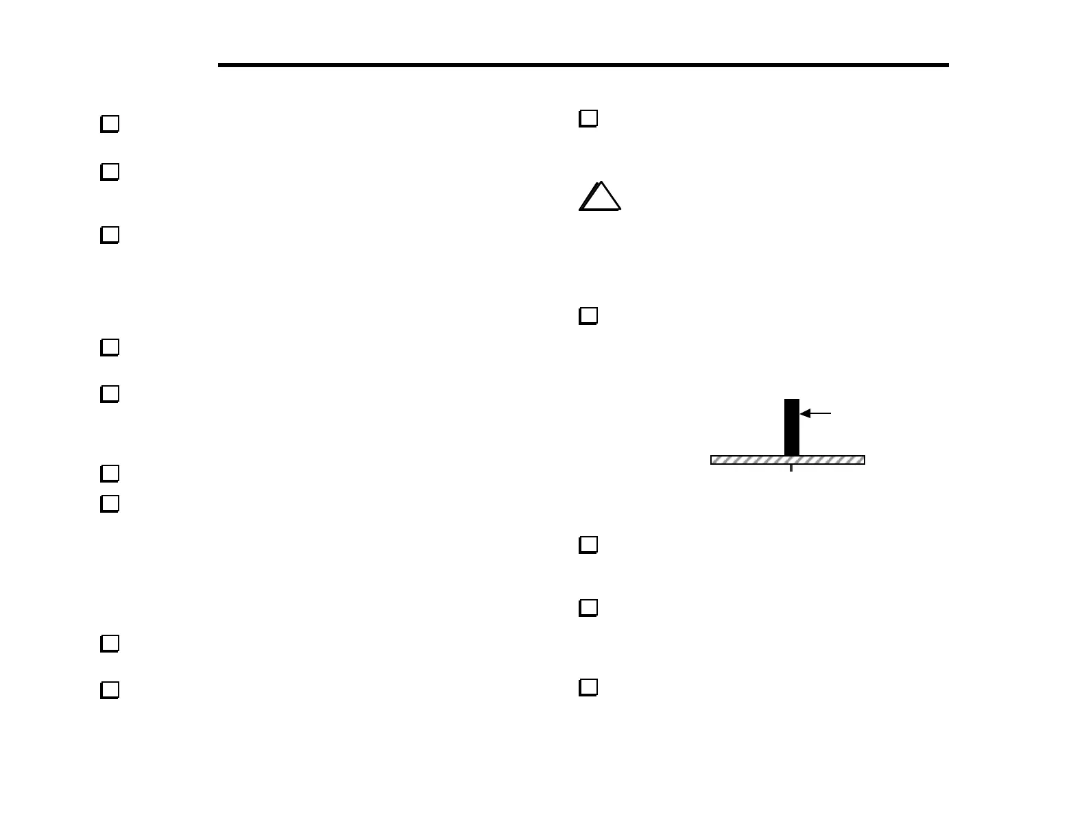
Install the 6-pin, single-row female connector, J6, which is just
left of the power switch. It must be seated vertically on the board
and must not be tilted (Figure 6-4). Solder just one pin near the
center of J6.
J6
Figure 6-4
If J6 does not appear to be completely flush with the board,
re-heat the soldered pin and press down. Once it is installed
correctly, solder the remaining pins.
Install the 20-pin, dual-row female connector, J8, near the
front left corner of the board. Use the same technique you used for
J6. This connector must be seated flush with the board before
soldering.
Install 36-pin dual-row female connector J7 in the same
manner as J6 and J8.