40 ELECRAFT
Plug the Control board assembly into the RF board, with the
component side of the Control board facing backwards. (Refer to
the photos in Appendix D.) All three connectors on the Control
board must be lined up with the three connectors on the RF board at
all pins.
Make sure the Control board is pushed as far down as it will go;
it should be flat against the RF board along its entire edge, with all
three connectors properly mated.
i
If the Control board does not plug in easily, you may have
one or more connectors installed incorrectly.
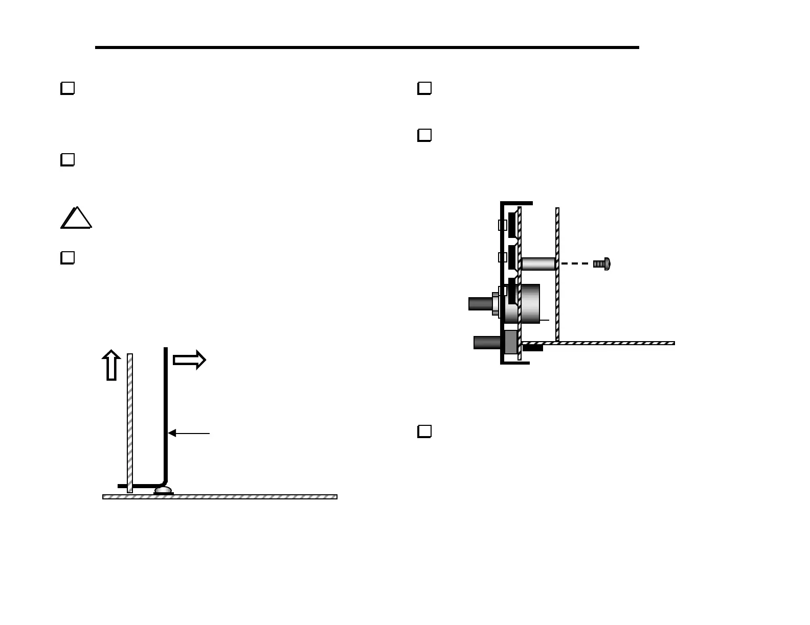
The long-handled Allen wrench can be used to extract the
Control board (Figure 6-11). To the left of J7 on the RF board
you’ll find the label "LIFT" near a hole at the base of the Control
board. Insert the Allen wrench into this hole, then rest the knee of
the wrench on the nearby screw head. Pry the board up with the
wrench while guiding the board out at the top.
Long-handled
allen wrench
Figure 6-11
Once you have tried the Control board extraction technique
described above, plug the Control board back in for the tests that
follow.
Secure the front panel and Control boards together using two
chassis screws (Figure 6-12). The upper left and right corners of the
Control board may be touching the 2-D fasteners, or there may be a
small gap.
Figure 6-12
Push the black keycap onto S1’s plunger until it snaps into
place. Test S1’s action (push on, push-off). Leave the switch in the
OFF position (out).