42 ELECRAFT
Turn the K2 off and wait for a few seconds, then turn it back
on. The display should now show E L E C R A F T for about two
seconds, followed by the frequency display. Now that the EEPROM
is initialized, this is the display you should always see on power-up.
The "R" and "T" in "ELECRAFT" appear in lower-case letters due
to the limitations of the seven-segment LCD characters.
Tap the D I S P L A Y switch once to select voltage/current
display. The display should now show something similar to this:
E 1 2 . 0 i 0 . 0 6
This would indicate that the power supply voltage (E) is about 12.0
V, and the supply current (I) is about 60-80 mA.
7
Optical Encoder Test
Tap the D I S P L A Y switch to return to the frequency display.
Turn the VFO knob in both directions and verify that the
displayed frequency changes accordingly.
Tap the
R A T E switch to the right of the knob to change the
tuning rate, and repeat the VFO test at each rate.
Relay Test
Tap the B A N D + switch. You should see the band change to the
next higher band. At the same time, you’ll hear one or more relays.
Tap the B A N D + switch 7 more times to verify that you hear
relays being switched with each band change. Note: The 1.8 MHz
(160 m) and 5 MHz (60 m) bands will not appear in the band list
unless the associated options are installed. This can be done only
after assembly and alignment have been completed.
7
The supply voltage reading will reflect a small drop across D10, the reverse-
polarity protection diode, typically 0.1 V on receive. Accuracy of both current
and voltage readings is about +/- 5%.
Tap the P R E / A T T N switch three times. You should hear relays
switch each time.
RF Probe Assembly
The Switch Spacing Tool used during Front Panel can now be used
as the PC board for the RF probe. All parts for the probe, including
a ground alligator clip, 2 feet of RG174 coax, and banana plugs for
a DMM, are supplied with the kit. You can assemble the probe at
any time, using the instructions on page 9 of Appendix E.
Voltmeter Probe Assembly
If you do not have a DMM (digital multimeter), you can use the
simple DC voltage probe shown below in conjunction with the built-
in voltmeter. The crimp pin and 2-pin housing can be found in the
MISCELLANEOUS components bag.
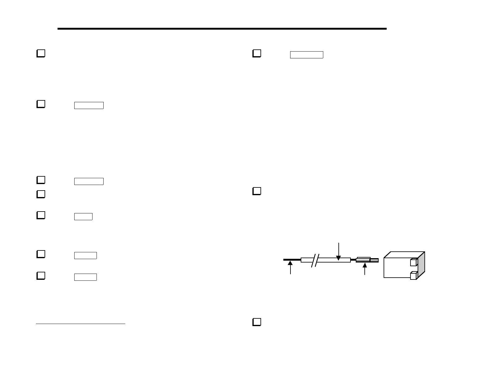
Assemble the voltage probe as shown in Figure 6-13 using
green-insulated hookup wire. No ground connection is needed since
you will be measuring voltages inside the K2.
Hookup wire,
12” (0.3m)
Crimp pin
Housing
Tinned lead,
0.5” (13mm)
Figure 6-13
Plug the voltage probe assembly into P5 on the Control board.
The probe should be oriented so that the hookup wire is connected
to the (+) side of P5.