44 ELECRAFT
Using the Calibration Functions
Scroll the menu until you see C A L O F F . This is the entry point
into the calibration sub-menu, which you’ll be using during
alignment.
Enter EDIT mode by holding
E D I T as before, moving the underline
to the O F F parameter. Then turn the VFO knob to see the various
C A L functions, including F C T R (frequency counter), C U R
(transmit current limiting) S H I / S L O (S-meter calibration),
F I L (crystal filter configuration), and P L L (VFO calibration).
Once you select a C A L function, holding
E D I T again activates the
function. The selected C A L function remains active until you tap
M E N U again, which returns you to the menu. Another tap of M E N U
returns you to the normal K2 display.
In the following section you’ll activate the C A L F C T R
(frequency counter) function. For now, just tap
M E N U once or
twice to return to the normal display.
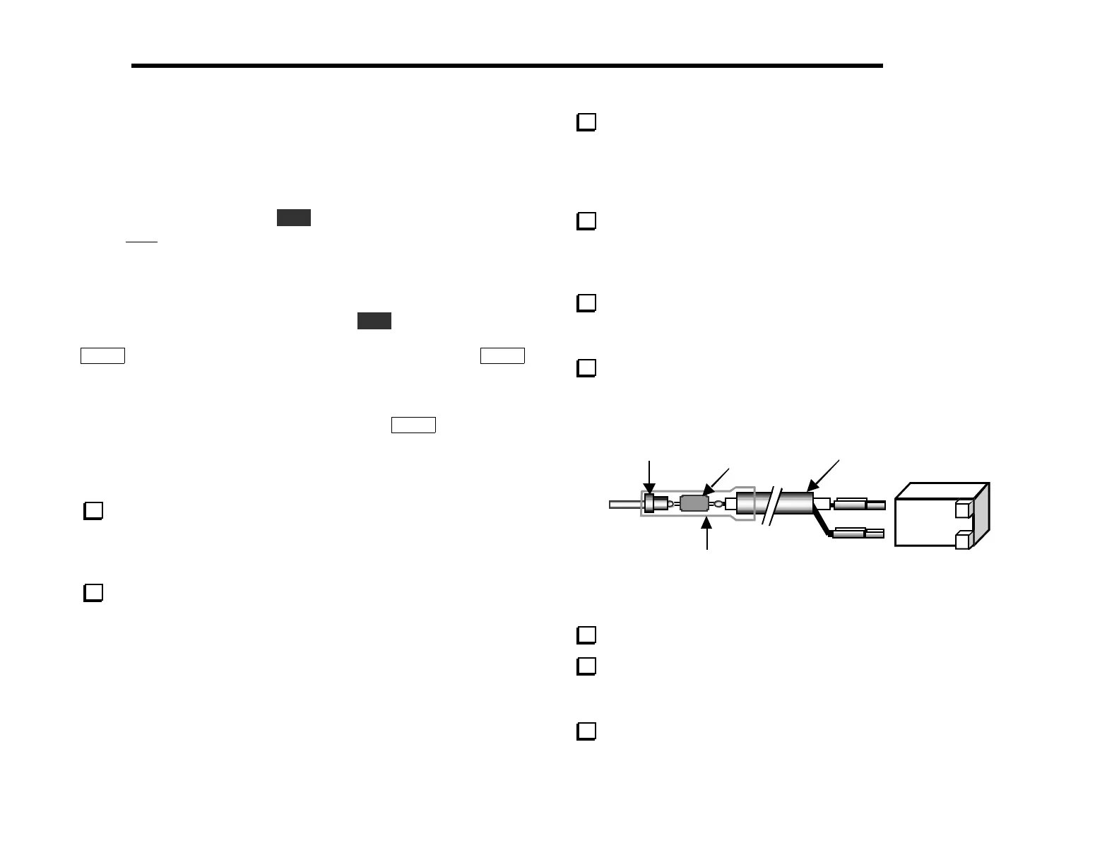
Frequency Counter Probe Assembly
In the bag labeled MISCELLANEOUS you’ll find the
components for the frequency counter probe (Figure 6-14). These
components include a 10 pF axial-lead capacitor, two crimp pins, a
2-pin housing, and a 1-pin male connector (probe tip).
Cut a 7" (18 cm) length of RG-174 cable and carefully remove
1/2" (13 mm) of the coax jacket from each end. Be careful not to
nick the braid.
Separate the braid from the center conductor at both ends.
Remove 1/4" (6 mm) of insulation from each center conductor. At
one end, cut the braid off completely right at the coax jacket (a
ground connection will not be needed for frequency measurements).
The braid should be twisted into a fine bundle at the other end.
Solder crimp pins onto the center conductor and shield at the
housing end of the cable. Solder quickly, so that the heat from
soldering does not melt the center insulator of the coax and cause a
shield-to-center short.
Insert the pins into the crimp housing as shown in Figure 6-14.
They should snap into place. Each crimp pin has a small tab on the
back that latches into a hole in the housing.
Trim the leads of the 10 pF axial-lead capacitor down to 1/4"
(6 mm). Solder one end to the center conductor of the coax cable.
RG-174 Coax,
7” (18cm)
Crimp housing
Probe
tip
10pF
eat-shrink tubing (2 layers)
Figure 6-14
Solder the probe tip to the other end of the 10 pF capacitor.
Slip a 1" (2.5 cm) length of the larger size heatshrink tubing
onto the probe tip components. Shrink the tubing using a heat gun.
(You can also use a soldering iron, but avoid melting the tubing.)
Add a second, identical length of heatshrink tubing on top of
the first, then shrink it. This strengthens the assembly.