50 ELECRAFT
Locate the crystals used on the RF board: 12.096 MHz (1),
4.9152 MHz for BFO (2) and 4.9136 MHz for crystal filters (7).
Do not mix the BFO and filter crystals, which have different
characteristics.
The bag of 7 filter crystals should have a number written on it.
Record the number here: ___________. (This identifies the tested
frequency of the crystals, and can be used in aligning filters.)
Install the 12.096 MHz crystal, X1, at the lower left. The
crystal should be seated flat on the board before soldering (it is OK
to bend the pins to hold it to the board). X2 is not used.
To the left of X1 (along the edge of the board) you’ll find a
pad for grounding the crystal case. Use short lengths of bare wire to
ground the crystal on at the top of the can.
Install the BFO crystals at X3 and X4 (near J7). Important:
trim X3's leads, and fold them down flat against their pads, before
soldering. Then use a minimal amount of solder. This is necessary to
avoid interference between X3 and L33 in a later step.
Ground the cases of X3 and X4. The ground pads are to the left
of the crystals.
Install the 4.9136 MHz filter crystals at X5 through X11.
Ground the cases of X5 and X6. The ground pads are near
where the two crystals meet.
A special grounding technique is required for X7-X11.
There are two ground pads for each of these crystals, one on either
side. Use bare wires (10 total) for grounding the crystals as you did
in previous steps, but do not solder the wires to the tops of the
crystals. The wires must be soldered to the sides of the crystals,
instead, about 1/4" (6 mm) up from the surface of the PC board.
Be very careful not to overheat the crystals. Use a
temperature-controlled iron, and limit soldering time to
about 3 seconds per soldering attempt.
i
In the following steps you’ll install several toroidal
inductors. Use the number of turns indicated. Do not attempt
to alter the turns to match inductances specified in the parts list.
Sort the black and dark gray toroidal cores into three groups to
avoid mis-identifying them in later steps. You should have eight
FT37-43 ferrite cores (3/8", 9.5 mm); four T44-10 iron powder
cores (0.44", 11 mm); and one FT50-43 ferrite core (0.5", 12.7
mm). Ferrite cores are dark gray; T44-10 cores are black.
Locate a 3/8" (9.5 mm) diameter ferrite toroidal core (type
FT37-43) as described above.
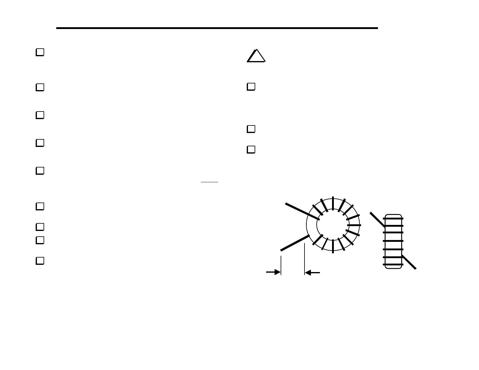
Find RFC14’s component outline on the RF board, near the
front left-hand corner. Compare this component outline to Figure
6-15, which shows two views of a typical toroidal inductor. RFC14
will be mounted vertically as shown at the right side of the drawing,
with one wire exiting at the core’s upper left, and the other at the
lower right. There are pads on the PC board in these two locations.
Remove insulation
Figure 6-15
Note: Toroid illustrations such as the one above do not
always show the actual number of turns used.
 Loading...


