62 ELECRAFT
Install the following 1/4-watt resistors, starting with R46
which is just to the left of I/O controller U1.
__ R46, 270 (RED-VIO-BRN) ⇒ __ R45, 47 (YEL-VIO-BLK)
__ R59, 4.7 k (YEL-VIO-RED) __ R61, 120 (BRN-RED-BRN)
__ R49, 120 (BRN-RED-BRN) __ R40, 470 (YEL-VIO-BRN)
__ R41, 560 (GRN-BLU-BRN) __ R55, 33 (ORG-ORG-BLK)
__ R53, 4.7 ohms (YEL-VIO-GLD)
__ R56, 33 (ORG-ORG-BLK)
__ R54, 4.7 ohms (YEL-VIO-GLD)
__ R60, 100 ohms (BRN-BLK-BRN)
__ R62, 2.7 k (RED-VIO-RED)
__ R67, 1.5 k, 1% (BRN-GRN-BLK-BRN)
__ R68, 226 ohms, 1% (RED-RED-BLU-BLK)
i
The 150 pF and 3.3 pF capacitors to be installed below
may be hard to identify. See capacitor information on page 9.
Install the capacitors listed below. C12 is near the back left
corner. Note: C13 and C14 will not be installed; they are included
with the 160 m/RX Antenna option (K160RX).
__ C12, 560 (561) ⇒ __ C11, 1800 (182) ⇒ __ C26, .001 (102)
__ C16, 1800 (182) __ C15, 560 (561) __ C22, 3.3 pF (3.3)
__ C20, 47 (47) __ C19, 330 (331) __ C30, 470 (471)
__ C24, 47 (47) __ C25, 330 (331) __ C35, 56 (56)
__ C37, .001 (102) __ C36, 470 (471) __ C33, 2.2 pF (2.2)
__ C49, .001 (102) __ C31, 56 (56) __ C42, 330 (331)
__ C43, 33 (33) __ C48, 330 (331) __ C47, 33 (33)
__ C45, 1 pF (1) __ C115, .01 (103) __ C117, .047 (473)
__ C118, .01 (103) __ C116, 33 (33) __ C121, 0.01 (103)
__ C120, .01 (103) __ C131, 0.1 (104)
__ C124, 0.1 (104) __ C130, 0.1 (104) __ C128, 680 (681)
__ C129, .01 (103) __ C127, 680 (681) __ C191, 1800 (182)
__ C190, 1200 (122) __ C197, 100 (101) __ C198, 27 (27)
__ C210, 82 (82) __ C211, 10 (10) __ C218, 150 (151)
__ C219, 12 (12) __ C138, .047 (473) __ C222, 100 (101)
__ C221, 39 (39) __ C220, 220 (221) __ C214, 68 (68)
__ C213, 33 (33) __ C212, 150 (151) __ C203, 47 (47)
__ C199, 220 (221) __ C200, 150 (151) __ C202, 120 (121)
__ C201, 220 (221) __ C192, 1200 (122)
i
There are two types of ceramic trimmer capacitors used in
the band-pass filters: 30 pF and 50 pF. These may look identical.
They will either be bagged separately, or the 50-pF trimmers will
have a red marking.
Install the trimmers listed below, starting with C21 near the
back-left corner. Orient the flat side of each trimmer capacitor
with the flat side of its component outline. This orientation is
required to prevent RF pickup during alignment.
__ C21, 50 pF __ C23, 50 pF
__ C32, 30 pF __ C34, 30 pF
__ C44, 30 pF __ C46, 30 pF
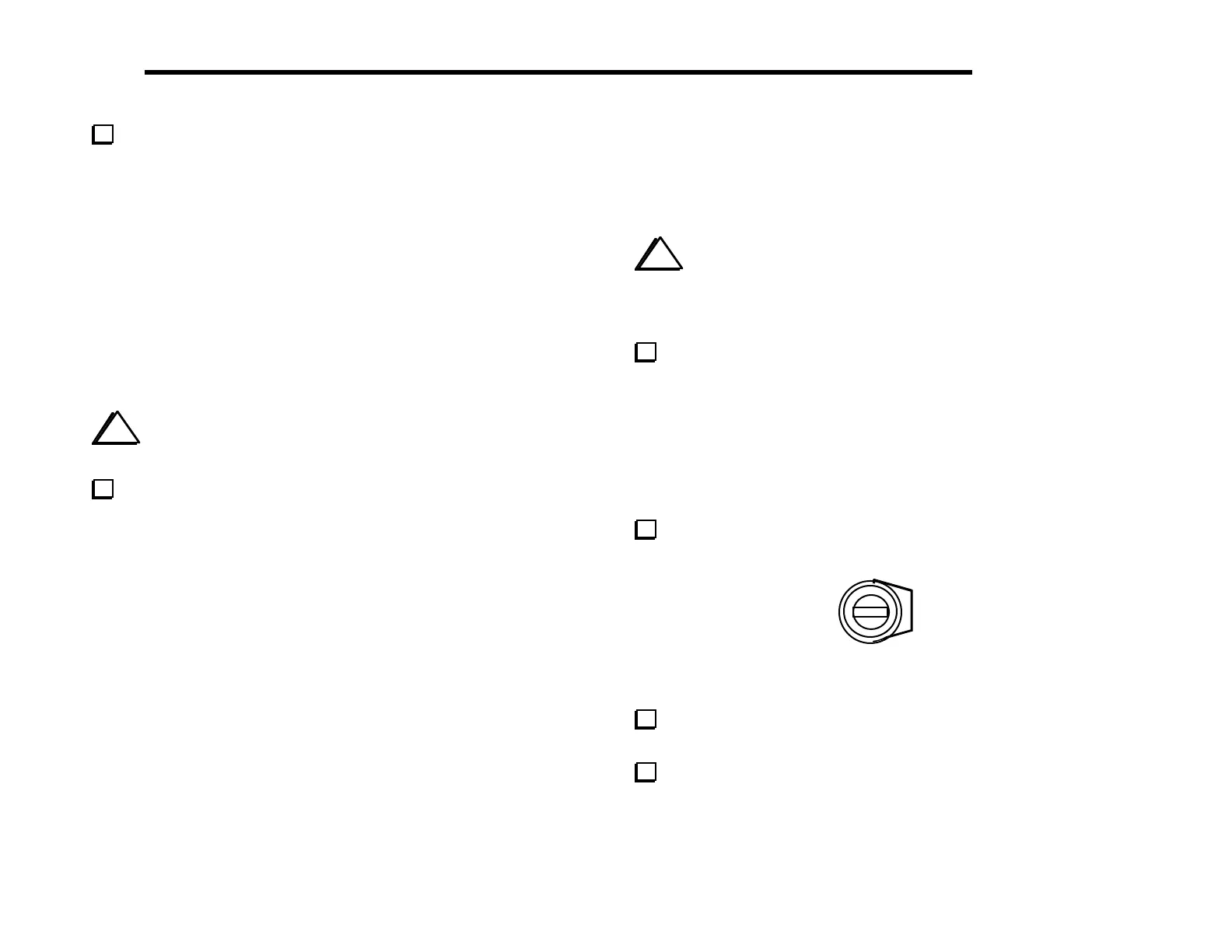
Set all of the trimmer capacitors just installed to their mid-way
points (see Figure 6-23). Use a small flat-blade screwdriver.
Figure 6-23
Install L5, a 33 µH RF choke (ORG-ORG-BLK), near the
back-left corner.
Install the following transistors, which are located near the I/O
Controller (U1).
__ Q10, 2N7000 __ Q11, PN2222A __ Q13, PN2222A