ELECRAFT 77
Finishing Touches
Examine the Control board one last time to be sure that it is
correctly plugged into the RF board. All three connectors must be
mated completely.
Leave the frequency counter test cable connected to the BFO
test point (TP2). This will allow you to modify your filter and BFO
settings if necessary during normal operation.
If there are any missing chassis screws in the bottom cover,
heat sink, side panels, or front panel, install them now.
Plug the internal speaker cable into P5 on the RF board, just
behind the on-off switch, S1. The connector is keyed and can only
be plugged in one way.
i
Even if you have purchased some K2 options, you should
not assemble and install them yet. The option manuals assume that
you are familiar with basic K2 operation.
Remove the masking material from the two top-cover
mounting holes marked C in Figure 7-1.
Cut through and peel off about 1/2" x 1/2" (12 x 12 mm) of
masking material from around the top-cover mounting holes
marked D in Figure 7-1. These holes are in the far corners of the
top cover's rear panel, corresponding to screws 1 and 2 in Figure
7-6.
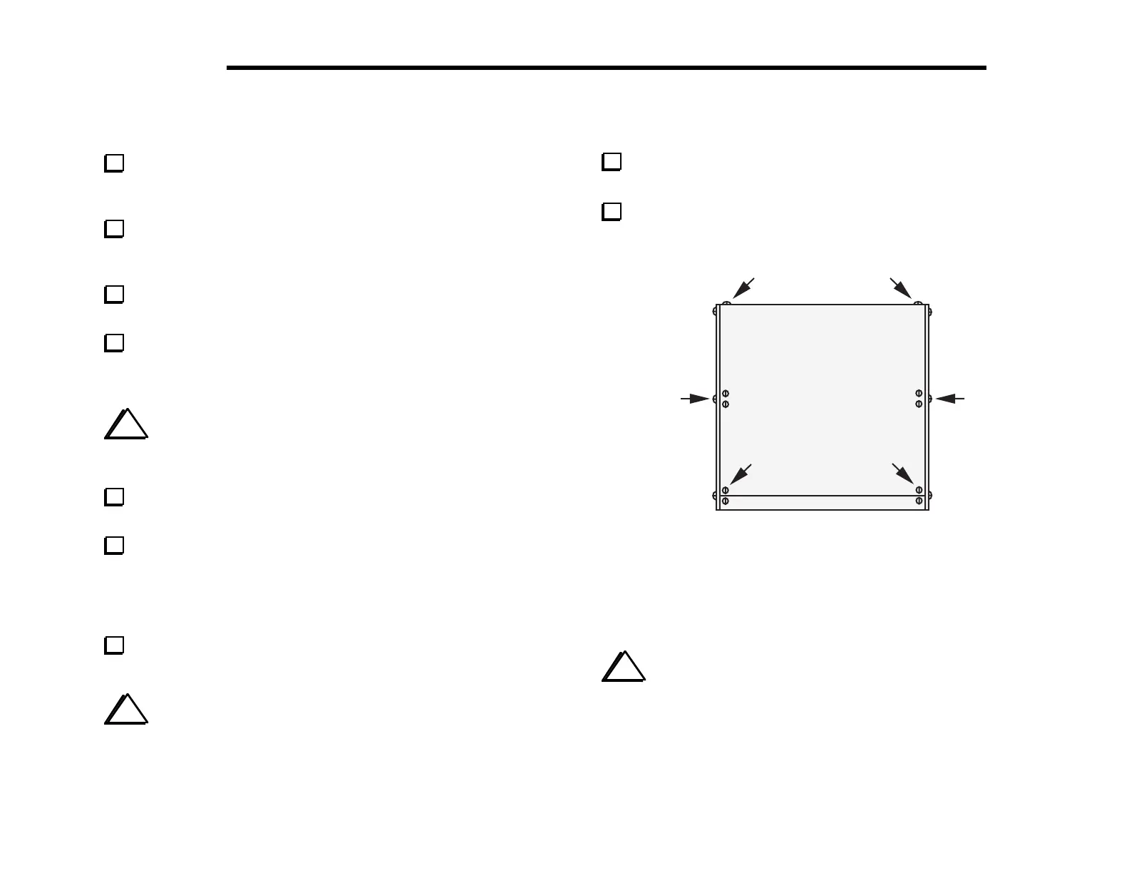
Place the top cover onto the chassis and secure it using six
chassis screws as shown in Figure 7-6.
i
When removing the top cover in the future, take out only
the six screws shown in Figure 7-6.
Attach the self-adhesive serial number label to the rear panel
of the heat sink in the space provided.
Write the serial number on the inside cover of your manual.
12
3
4
56
Figure 7-6
This completes assembly of your K2. Please read the Operation
section, which follows, and try each of the K2's features.
i
If you did not have access to a frequency counter or
calibrated receiver when aligning the 4-MHz oscillator, you may
wish to use the one of the alternative VFO calibration techniques
described in the Operation section (page 98). You can use an on-air
signal, such as WWV at 10 MHz, to obtain better than +/- 50 Hz
VFO dial calibration on all bands.