ELECRAFT 51
Install toroidal inductor L3 and solder both leads. Check for
continuity (less than 1 ohm) between the solder pads.
i
Do NOT attach L3 or T1 to the circuit board with adhesive
or other compounds. They should be supported only by their
leads.
Install two pairs of standoffs in the holes at the edges of the board
as shown in
Figure 20. The front panel / top cover will attach to the
short standoff. One pair of standoffs installs near J8 and K2 (on the
bottom face of the board) and the other pair installs in the hole near J1
and P6.
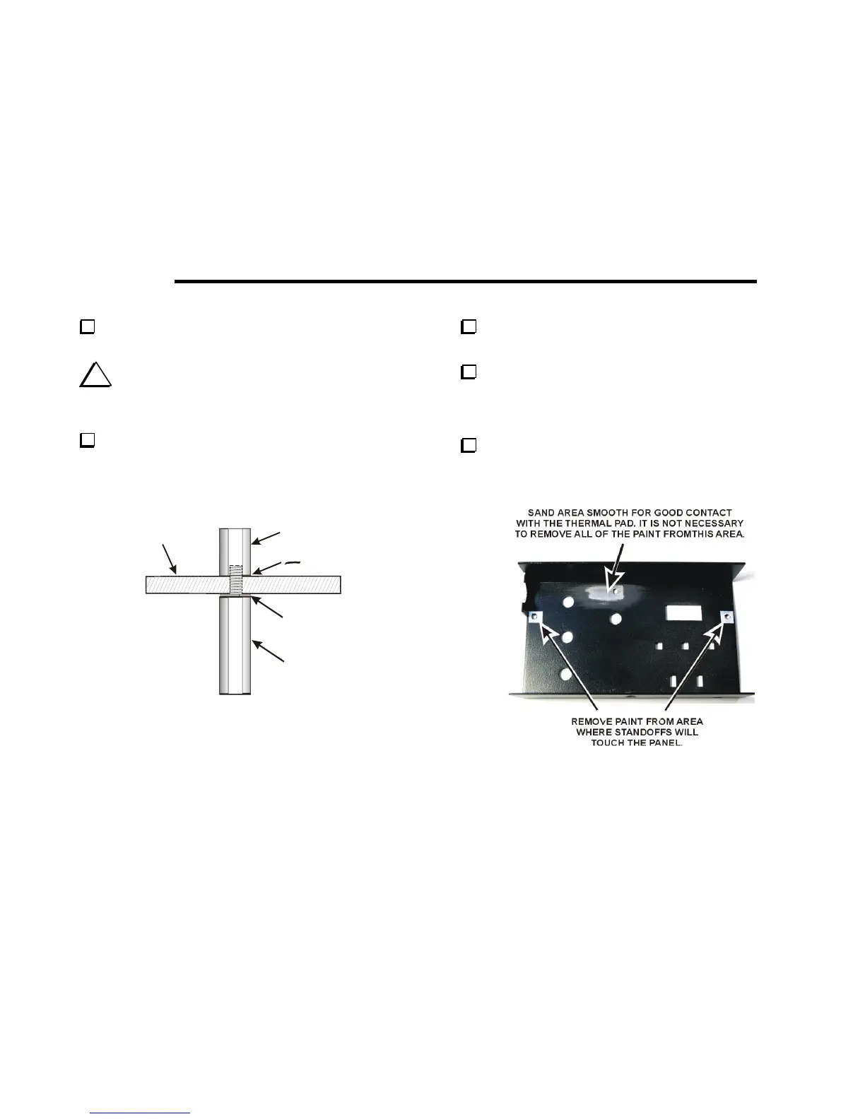
5/16” STANDOFF
T
F
BOARD
3/4” STANDOFF
SPLIT WASHER
NO
WASHER HERE!
Figure 20. Installing Standoffs on Circuit Board.
Place the front panel (top cover) face down on a soft cloth to
avoid scratching it.
Remove the paint from around the screw holes where the short
standoffs will contact the front panel as shown in
Figure 21. Use
sandpaper or a sharp knife. Clean the panel thoroughly to remove all
of the residue when you are done.
Inspect the area where the thermal pad will mount and be certain
there are no burrs that could poke through the thermal pad. Burrs are
most likely to be found around the hole. Sand file any rough edges
smooth.
Figure 21. Preparing Top Cover for Installation.