ELECRAFT 53
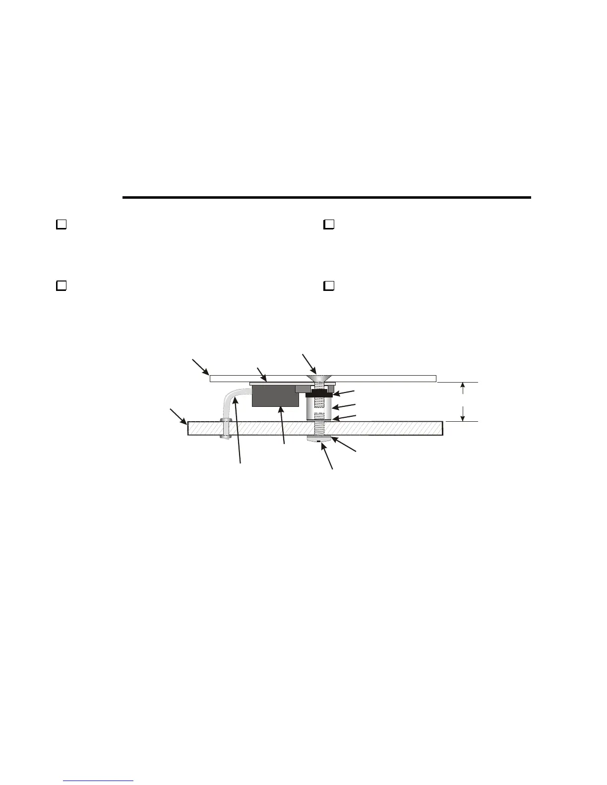
In the following steps you will install power amplifier transistor
Q6 (2SC2166). Q6 is mounted so that the front panel (top cover) will
act as a heat sink. Begin by studying how the final assembly will look
with the circuit board mounted in the case (see Figure 24), then follow
the steps below exactly as given.
Bend Q6’s leads in a gentle 90-degree curve. Note that the flat
side of the transistor faces away from the circuit board. Wrapping the
leads around a round screwdriver shaft or drill bit helps avoid sharp
kinks in the bend.
Locate the silk-screened outline for Q6 at the top edge of the
circuit board. Install the 3/16” (4.76 mm) standoff on the circuit board
using a 3/16” pan head screw and two split washers as shown in the
figure. The split washer under the standoff is important to reach
the proper height so Q6 will come in contact with the cover.
Place Q6’s leads in the holes in the circuit board. Do not solder
them until instructed to do so.
FRONT (TOP)
PANEL
THERMAL PAD
2SC2166
TRANSISTOR
3/16” PAN HEAD
SCREW
3/16” STANDOFF
0.31” (7.87mm)
SPLIT WASHER
SPLIT WASHER
SHOULDER WASHER
4-40 X 1/4”
FLAT HEAD
CIRCUIT BOARD
FORM LEADS IN
GENTLE CURVE
DO NOT MAKE
SHARP 90 BEND!
O
Figure 24. Installing Power Amplifier Q6.


 To Next Page