ELECRAFT 55
Turn the unit face down on a soft surface and measure the
resistance between either solder pad for toroid L3 and ground. It
should be > 500 ohms. If it is less, you must find the cause before
proceeding. Check the hardware around Q3. The most likely cause
will be that the shoulder washer has slipped out or the metal tab on the
transistor is touching the case instead of the thermal pad.
Install the knob on the encoder shaft.
Find the battery holders and inspect the bottom of one. Note the
ridges and nubs that provide a space for wires under the holder. The
holder has one wire running between two molded ridges that connect
the opposite corner cells together.
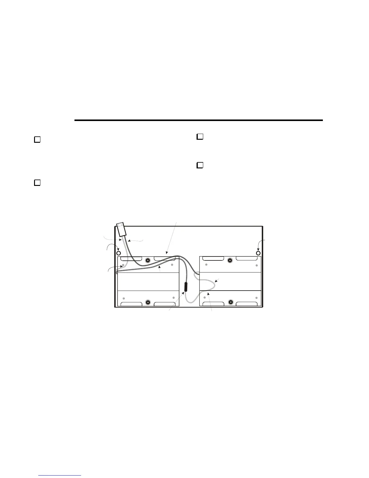
In the following steps you will install and wire the battery
holders. First, study the wiring drawing in Figure 25. The two holders
are wired in series. The wires must run against the bottom cover and
under the holders as shown to avoid interfering with other components
when the KX1 case is closed.
RED
2-3/4” (7 CM)
BLACK
CUT TO MATCH
LENGTH OF RED
R
UNDER BATTERY HOLDER
AND AROUND SCREW.
BE SURE WIRES LIE FLAT AND
DO NOT CROSS OVER EACH OTHER.
BLACK
4” (10.2 CM)
RED
3-1/4” (8.3 CM)
ROUTE RED
WIRE UNDER
BATTERY
HOLDER AND
AROUND
CORNER
NUB
SPLICE MUST LIE FLAT ON BOTTOM.
KEY JACK J3 AND CRYSTALS ON THE
BOTTOM OF THE CIRCUIT BOARD FIT IN
THI