Radio Fire Alarm System – User Manual Page:4
V301_user Feb 2009
Electro-Detectors
2 Basic Operation
In order to operate the panel the front panel door will have to be unlocked.
(Note: This section describes operation of a system with standard configuration.
Operation is for the EDA-M100 and EDA-M150 unless otherwise stated)
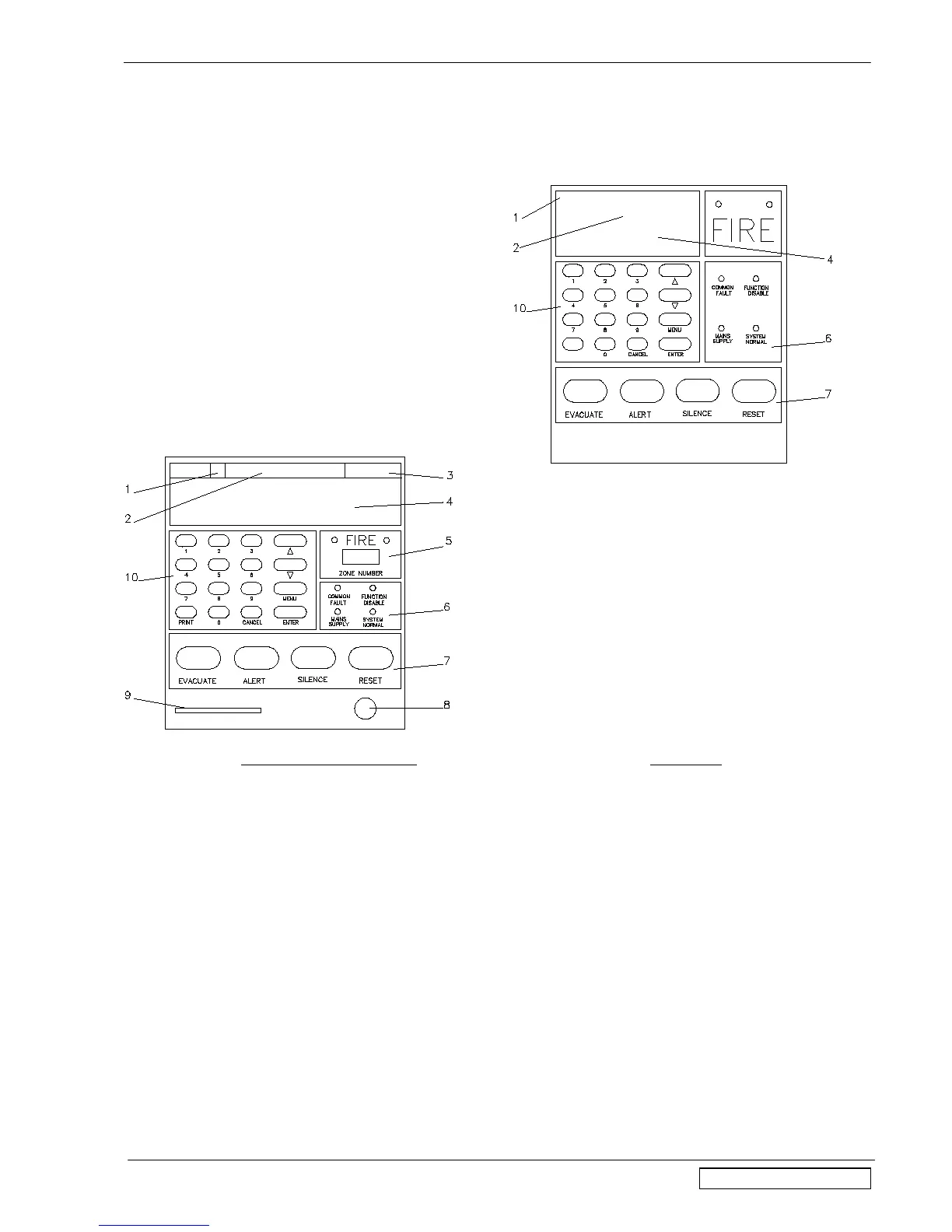
EDA-M100 and EDA-M150 EDA-M200
2.1 Normal When no faults or alarms are being displayed, the display will appear dark. The current time and date
are displayed in area (3), not available on the EDA-200. The installing agents name and telephone
number will be displayed in area (2). Whenever a radio message is received or transmitted the
appropriate Rx or Tx box (1) will flash. Nothing will be displayed in area (4). The system Normal LED
(6) will be illuminated. The mains supply light will be illuminated indicating the supply is healthy.
2.2 Fault When the panel detects a fault condition the internal buzzer will sound continuously and the common
fault light will illuminate. The display back light will be switched on and the initial fault will be displayed
on the first line, as shown in the example below. The display will detail the type of fault, which device
and when it occurred. If programmed, a text location will be displayed below. The EDA-M200 is not
capable of detailing dates and times for any of its events. Any subsequent faults will be displayed, and
scroll through, on the bottom two lines of the display. The EDA-M200 will only display one fault at a
time. Each fault is visible for a short period of time. Pressing the ↑ and ↓ keys will cause either the
previous or the next fault to be displayed. This will then continue to scroll from the event being
displayed. It is possible for 300 faults to be scrolled through. Window (3) will alternate between the
total fault count and the date and time. The installing agents name and telephone number remains in
area (2) of the display. In order to conserve power the LCD backlight will switch off 15 minutes after a
fault occurs on any panel. If the mains supply is interrupted the fault will be indicated as above and
the Mains Supply light will be extinguished. For a complete list of faults see appendix 5.0.
The default fault relay is AUX 2 but may be reconfigured.