X-Array™ Loudspeaker Systems
and bottom for the attachment of two Xrhg, Xrhl
or Xrhp rigging hinges. The track/bracket assem-
bly is extruded as a single piece. One assembly
ties into the back and top of the enclosure, while
a second assembly ties into the back and bottom
of the enclosure. High-strength, aluminum-alloy
bars inside the enclosure tie the top and bottom
track/bracket assemblies together, minimizing
the load applied to the enclosure shell. The track
dimensions are similar to the widely used heavy-
duty aircraft L-track (such as the New Haven
NH34030-3HD or ATM Fly-Ware™ ATM-TRACK).
The cutouts in the rear rigging track are shown in
Figure 3a. The large cutout in the center of the
track is for inserting the rigging hinges. The small
holes in the base of the track are for locking the
rigging hinges. The round cutouts on either side
are provided so that two New Haven NH32102-2
double-stud swivel-ring fittings may be installed
for light-duty lifting applications and for pull-ups.
Key dimensions for the rear rigging hardware are
presented in Figure 3a. (See section
3. Rigging-
Strength Ratings, Safety Factors and Special
Considerations
for a detailed discussion of the
structural strength of the enclosure rear rigging
points.)
At the front of the enclosure is another pair of
proprietary high-strength, aluminum-alloy track/
bracket assemblies which are also extruded as a
single piece. One assembly ties into the left side,
top, bottom of the enclosure, while a second as-
sembly ties into the right side, top and bottom of
the enclosure. The front track extends from the
top to the bottom on both sides of the enclosure,
eliminating the load applied to the enclosure shell.
These track dimensions are also similar to the
widely used heavy-duty aircraft L-track (New
Haven NH34030-3HD or ATM Fly-Ware™ ATM-
TRACK). On both sides of the enclosure, the front
rigging track has six cutouts near the top and
bottom, as shown in Figure 3b. The New Haven
NH32102-2 double-stud swivel-ring fittings on
the Xrss and Xrsl wire-rope rigging straps may be
installed at any of the cutouts. The relative angle
between a pair of enclosures (or the top enclo-
sure and the grid) is set by the position of the
front rigging-strap fittings in the track cutouts.
Key dimensions for the front rigging hardware
are presented in Figure 3b. (See section
3. Rig-
ging-Strength Ratings, Safety Factors and Special
Considerations
for a detailed discussion of the
structural strength of the enclosure front rigging
points.)
To facilitate the installation and removal of the
linking hinges, alignment feet are installed on the
top and bottom of the X-Array™ enclosures. Male
feet (protruding feet) are located on the bottom
of the enclosures, while female feet (concave
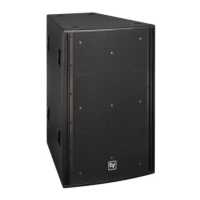
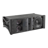
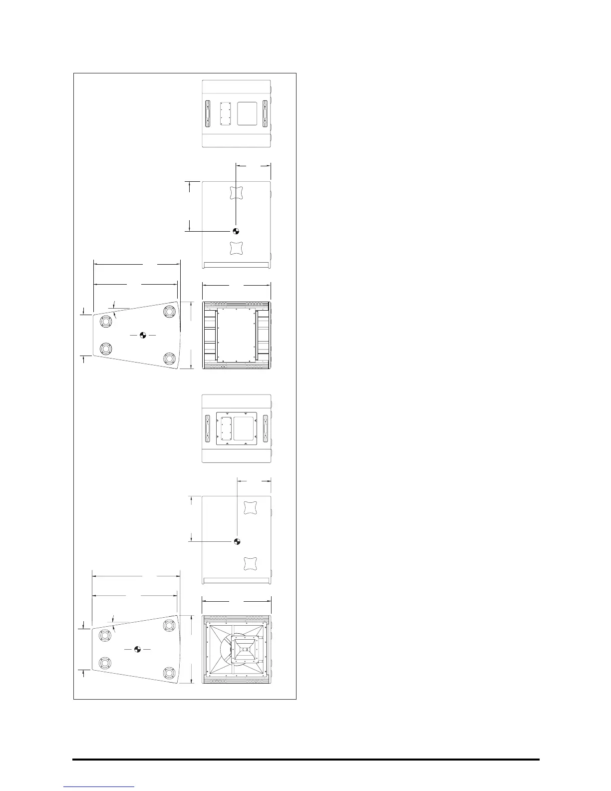
FIGURE 2e - Xcn SYSTEM
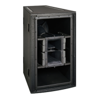
FIGURE 2 (cont’d) - X-ARRAY LOUDSPEAKER SYSTEMS
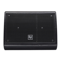
FIGURE 2f - Xcb SYSTEM
595.9 mm
(23.46 in.)
(23.00 in.)
584.2 mm
758.8 mm
(29.88 in.)
353.8 mm
(13.93 in.)
733.2 mm
(28.87 in.)
9.0°
TYP
C
L
WEIGHT: 60.8 kg (134 lb)
292.1 mm
(11.50 in.)
391.2 mm
(15.40 in.)
595.9 mm
(23.46 in.)
433.6 mm
(17.07 in.)
301.6 mm
(11.88 in.)
WEIGHT: 55.8 kg (123 lb)
758.8 mm
(29.88 in.)
C
L
9.0°
TYP
733.2 mm
(28.87 in.)
584.2 mm
(23.00 in.)
353.8 mm
(13.93 in.)
page 4