23
E30SO75ESS
TEST PROCEDURES
PROCEDURE
LETTER
COMPONENT TEST
W SOLID-STATE RELAY TEST
Solid-state rela
21
43
1. Disconnect the power supply and then remove outer case.
2. Open the door and block it open.
3. Discharge high voltage capacitor.
4. Disconnect the wire leads from the solid-state relay.
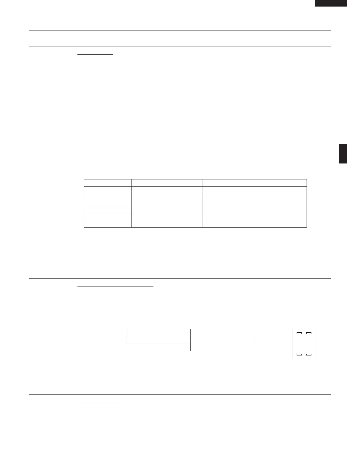
5. Measure the resistance between the terminals as described in the following table, with an ohmmeter.
Terminals Resistance
Between 1 and 2 Approx. 50MΩ
Between 3 and 4 Approx. 1.3MΩ
6. If the meter does not indicate above resistance, replace the solid-state relay.
7. Reconnect all leads removed from components during testing.
8. Re-install the outer case (cabinet).
9. Reconnect the power supply cord after the outer case is installed.
10.Run the oven and check all functions.
1. Disconnect the power supply cord, and then remove outer case.
2. Open the door and block it open.
3. Discharge high voltage capacitor.
4. Disconnect the leads to the primary of the power transformer.
5. Ensure that these leads remain isolated from other components and oven chassis by using insulation
tape.
6. After that procedure, re-connect the power supply cord.
7. Remove the outer case and check voltage between Pin Nos. 1 and 9 of the 5 pin connector (CN-D)
on the control unit with an A.C. voltmeter. The meter should indicate 240 volts, if not check oven
circuit.
Shut-off, Cook and Heater Relays Test
These relays are operated by D.C. voltage
Check voltage at the relay coil with a D.C. voltmeter during the microwave cooking operation, speed
grill, speed roast, speed bake, or convection cooking condition.
DC. voltage indicated ............... Defective relay.
DC. voltage not indicated ........... Check diode which is connected to the relay coil. If diode is good,
control unit is defective.
RELAY SYMBOL OPERATIONAL VOLTAGE CONNECTED COMPONENTS
RY1 Approx. 27.0V D.C. Oven lamp / Turntable motor
RY2 (COOK) Approx. 25.0V D.C. Power transformer
RY3 Approx. 25.0V D.C. Convection motor
RY4 Approx. 25.0V D.C. Damper motor
RY5 Approx. 25.0V D.C. Fan motor
RY6 Approx. 25.0V D.C. Convection motor
8. Disconnect the power supply cord, and then remove outer case.
9. Open the door and block it open.
10.Discharge high voltage capacitor.
11.Reconnect all leads removed from components during testing.
12.Re-install the outer case (cabinet).
13.Reconnect the power supply cord after the outer case is installed.
14.Run the oven and check all functions.
V RELAY TEST
X DEFROST TEST
WARNING : The oven should be fully assembled before following procedure.
(1) Place one cup of water in the center of the turntable tray in the oven cavity.
(2) Close the door, touch the Compu Defrost pad and select “ Steaks/Chops ” by touching Up/Down