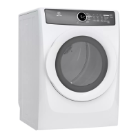
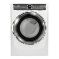
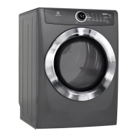
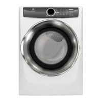
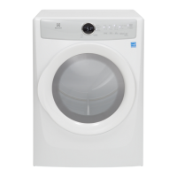
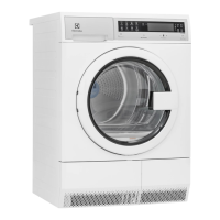
Do you have a question about the Electrolux EFME617SIW and is the answer not in the manual?
Details on the electronic control system components.
Information about the UI board and its functions.
Overview of the main electronic control board.
Wiring and component schematic for electrical systems.
Specific wiring diagram for electric models.
Specific wiring diagram for gas models.
Table of electrical component specifications and resistance values.
Details on the heating element for electric and gas dryers.
General characteristics of the heating element.
Information on the inlet control thermistor.
General characteristics of the inlet control thermistor.
Information on the outlet control thermistor.
General characteristics of the outlet control thermistor.
Details on door switch and drum light components.
General characteristics of door switch and drum light.
Information on the single-phase induction motor.
General characteristics of the induction motor.
Details on the inlet thermal limiter.
General characteristics of the inlet thermal limiter.
Details on the outlet thermal limiter.
General characteristics of the outlet thermal limiter.
Information on the high-limit thermostat.
General characteristics of the high-limit thermostat.
Information on the contact/moisture sensor.
General characteristics of the moisture sensor.
Details on the mist valve component.
General characteristics of the mist valve.
Information about the igniter in gas models.
General characteristics of the igniter.
Details about the burner assembly in gas models.
General characteristics of the burner assembly.
Information on the gas valve.
General characteristics of the gas valve.
Details on the flame sensor in gas models.
General characteristics of the flame sensor.
Instructions for accessing the lint filter.
Instructions for accessing the moisture sensor.
Steps to access the electronic control board.
Instructions for accessing the drum vanes.
Steps to access the mist valve from the rear.
Steps to access the NTC 2 thermistor.
Steps to access the NTC 1 thermistor.
Steps to access the fire containment thermostat.
Steps to access the outlet thermal limiter.
Steps to access the heater assembly for electric models.
Steps to access the inlet thermal limiter.
Steps to access the high-limit thermostat.
Steps to access the heater assembly for gas models.
Steps to access the flame sensor.
Steps to access the burner assembly.
Steps to access the igniter.
Steps to access the inlet thermal limiter for gas models.
Steps to access the high-limit thermostat for gas models.
Steps to access and replace the door switch.
Steps to access the user interface board assembly.
Instructions for accessing and replacing the drive belt.
Steps to access and replace the motor assembly.
Procedure to enter the diagnostic mode.
How to navigate through diagnostic tests.
Steps to exit the diagnostic mode.
Procedure for resetting to factory defaults.
Explanation of the demo mode functionality.
How to activate the demo mode.
Steps to disable or clear demo mode.
List and explanation of error codes displayed by the unit.
Troubleshooting steps for door open error.
Troubleshooting steps for drum motor relay errors.
Troubleshooting steps for heater relay errors.
Troubleshooting steps for NTC 1 (outlet thermistor) errors.
Troubleshooting steps for power supply frequency issues.
Troubleshooting steps for ventilation blockage errors.
Troubleshooting steps for safety reset errors.
| Color | island white |
|---|---|
| Dryer Capactity | 8.0 cubic feet |
| Number of Cycles | 9 |
| Options | steam; anti static; end-of-cycle chime; 4 timed dry selections selections; gentle tumble system |
| Stackable | yes |
| Control Type | led display with touchscreen controls |
| Delay Start | yes |
| Cycle Signal | yes |
| Interior Light | yes |
| Drying Rack | no |
| Moisture Sensor Option | yes |
| Steam | yes |
| Voltage | 120 volts |
| Current | 9.0 amperes |
| Depth | 31 1/2 inches |
|---|---|
| Height | 38 inches |
| Width | 27 inches |
| Net Weight | 130 pounds |


