CCoommppoonneenntt TTeeaarrddoowwnn
4-14
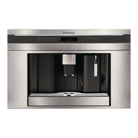
FFiigguurree 44--3300.. MMiiccrroosswwiittcchh RReemmoovvaall
Control Board
Screws
Blue
White
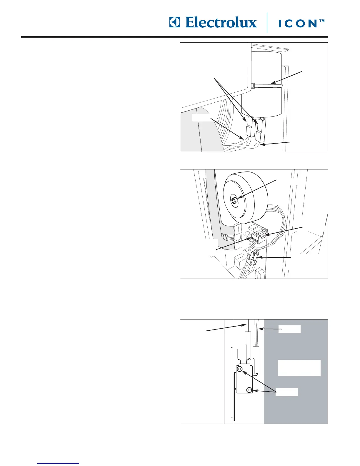
CCaappaacciittoorr RReemmoovvaall
The capacitor is located behind the right side access
panel and is secured to the unit frame with a tie-down
strap.
To remove the capacitor (See Figure 4-28):
1. Pull unit out from installation and remove from the
installation cavity if needed.
2. Remove right side access panel.
3. Disconnect electrical leads from capacitor.
4. Using a wire cutters, cut tie-down strap securing
capacitor to unit frame.
VVoollttaaggee TTrraannssffoorrmmeerr RReemmoovvaall
The voltage transformer is located behind the right side
access panel and is secured to the unit frame with a
large washer and bolt.
To remove the voltage transformer (See Figure 4-29):
1. Pull unit out from installation and remove from the
installation cavity if needed.
2. Remove right side access panel.
3. Disconnect blue electrical leads from quick
disconnect.
4. Using a very small flat-bladed screw driver, lift up
the retaining clips on the green wire terminal in the
upper right hand corner of the control board, while
pulling the wire terminal off the control board.
5. Using a small flat-bladed screw driver, loosen the
setscrews securing the two red wires leading to the
voltage transformer. Pull wires from wire terminal.
6. Using a 5mm allen wrench, remove bolt and large
washer securing voltage transformer to unit frame.
MMiiccrroosswwiittcchh RReemmoovvaall
The microswitch is located to the left of the control
board behind wire harness, and is secured with screws
to the unit frame. The microswitch is activated by a
standoff on the coffee grounds drawer.
To remove the control board (See Figure 4-30):
1. Pull unit out from installation and remove from the
installation cavity if needed.
2. Remove right side access panel.
3. Disconnect electrical leads from terminals of
microswitch.
4. Using a 2.5 mm allen wrench, remove screws
securing microswitch to unit frame.
FFiigguurree 4
4--2288.. CCaappaacciittoorr RReemmoovvaall
FFiigguurree 44--2299.. VVoollttaaggee TTrraannssffoorrmmeerr RReemmoovvaall
Disconnect
Wire Leads
Blue
Red
Tie-down
Strap
Bolt
Retaining
Clips
Wire
Terminal
Electrical
Disconnect