CCoommppoonneenntt TTeeaarrddoowwnn
4-15
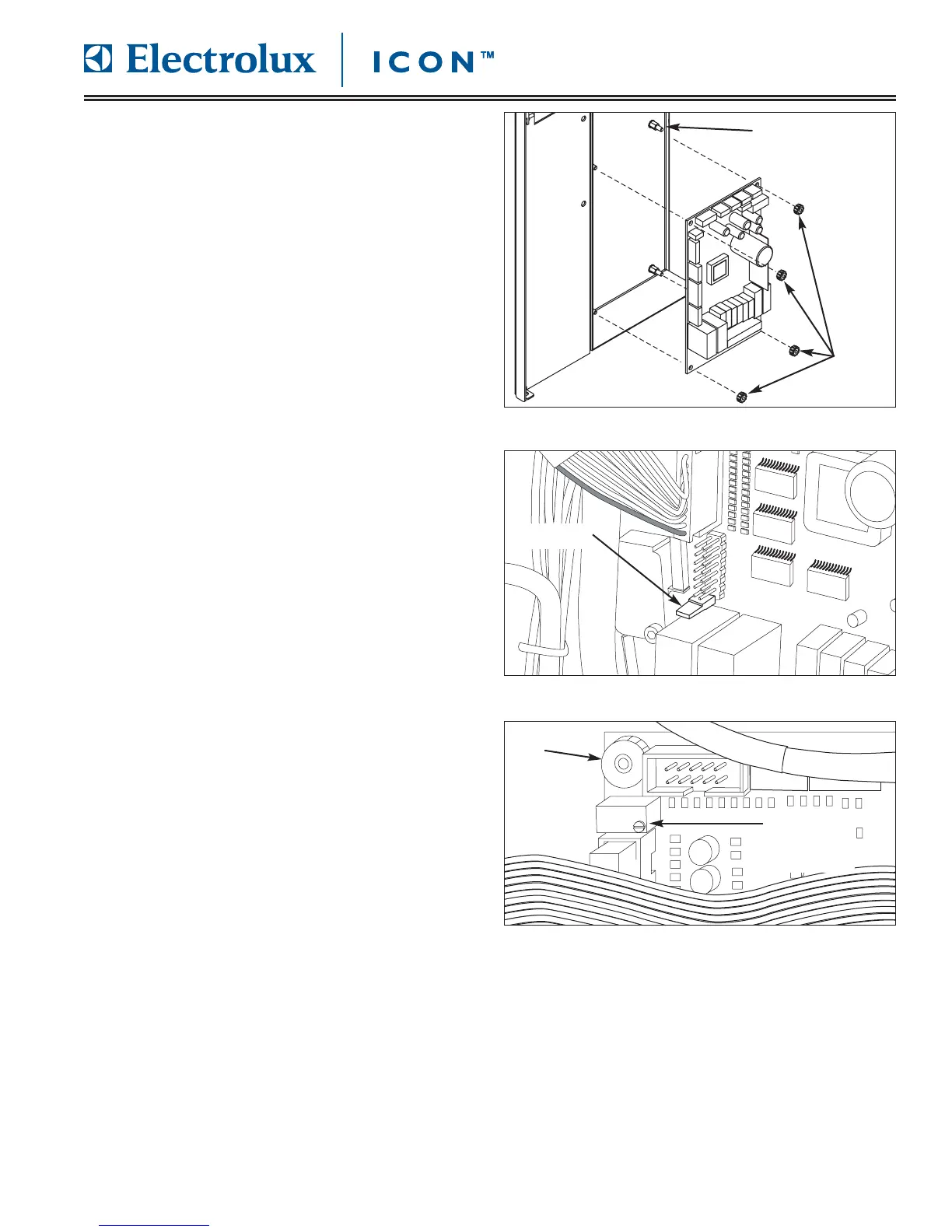
CCoonnttrrooll BBooaarrdd RReemmoovvaall
The control board is located behind the right side
access panel and is mounted to the unit frame on
threaded standoffs and secured with plastic finger nuts.
NNoottee::
The jumper from the old control board must be
reoved and mounted on the new control board.
To remove the control board (See Figure 4-31):
1. Pull unit out from installation and remove from the
installation cavity if needed.
2. Remove right side access panel.
3. Disconnect all electrical leads from control board.
4. Using fingers, remove nuts from each corner of
control board, then pull control board off threaded
standoffs.
5. A jumper is mounted to the bottom set of pins on
the 16 pin connecter. Remove jumper from old
control board and instal on new control board.
(See Figure 4-32)
6. When replacing a control board it may be neces-
sary to adjust the contrast of the user display. The
adjustment screw is located on the top of a small
blue housing located below the upper left control
board retaining nut. (See Figure 4-33)
The screw may be turned clockwise and counter-
clockwise to find the best setting for the user
display.
FFiigguurree 44--3311.. CCoonnttrrooll BBooaarrdd RReemmoovvaall
FFiigguurree 44--3322.. RReemmoovvee JJuummppeerr FFrroomm OOlldd BBooaarrdd
FFiigguurree 44--3
333.. RReemmoovvee JJuummppeerr FFrroomm OOlldd BBooaarrdd
Threaded Standoff
Nuts
Jumper
Contrast
Adjustment
Screw
Nut