EasyManua.ls Logo

Electrolux ICON Professional E30DF74GPS User Manual

Electrolux ICON Professional E30DF74GPS
12 pages
To Next Page IconTo Next Page
Page #1 background imageLoading...
Page #1 background image
1
30" & 36" DUAL FUEL RANGE INSTALLATION INSTRUCTIONS
(Model with Electric Oven and Gas Cooktop)
If the information in this manual is not followed exactly, a fire
or explosion may result causing property damage, personal injury or death.
FOR YOUR SAFETY:
Do not store or use gasoline or other flammable vapors and liquids in
the vicinity of this or any other appliance.
WHAT TO DO IF YOU SMELL GAS:
Do not try to light any appliance.
Do not touch any electrical switch; do not use any phone in your building.
Immediately call your gas supplier from a neighbor's phone. Follow the
gas supplier's instructions.
If you cannot reach your gas supplier, call the fire department.
Installation and service must be performed by a qualified installer, service
agency or the gas supplier.
P/N 318201773 (0706) Rev. A
English - pages 1-12; Español - páginas 13-24
Français - pages 25-36 ; Wiring Diagram - page 36
Note: Wiring diagram for this model is enclosed in this booklet (see page 36).
Printed in United States
INSTALLATION AND SERVICE MUST BE PERFORMED BY A QUALIFIED INSTALLER.
IMPORTANT: SAVE FOR LOCAL ELECTRICAL INSPECTOR'S USE.
READ AND SAVE THESE INSTRUCTIONS FOR FUTURE REFERENCE.
OBSERVE ALL GOVERNING CODES AND ORDINANCES.
B. WIDTH
29 7/8"
( 75.9 cm)
C. DEPTH TO
FRONT OF RANGE
27 1/2"
(69.9 cm)
E. DEPTH WITH
DOOR OPEN
45 1/2"
(115.6 cm)
F. HEIGHT OF
COUNTERTOP
36" (91.4 cm) Standard
35 3/4" (90.8 cm) Min.
G. MINIMUM
CUTOUT WIDTH
30 1/16"
(76.4 cm)
NOTE: 24" (61 cm) minimum clearance between the
cooktop and the bottom of the cabinet when the bottom
of wood or metal cabinet is protected by not less than
1/4" (0.64 cm) flame retardant millboard covered with
not less than No. 28 MSG sheet metal, 0.015" (0.4 mm)
stainless steel, 0.024" (0.6 mm) aluminum, or 0.020"
(0.5 mm) copper.
30" (76.2 cm) minimum clearance when the cabinet is
unprotected.
Do not pinch the power supply cord between the range
and the wall.
Do not seal the range to the side cabinets.
13" Max.
(33 cm Max.)
24" Min.
(61 cm Min.)
24 1/2" Max.
(62.2 cm Max.)
29 7/8" Min.
(75.9 cm Min.)
See
note
Grounded
Wall Outlet or
junction box
location
W
A
LL
WALL
If there is a wall:
7" Min.
(17.78 cm Min cm Min.)
Left side
18" Min.
(45.7 cm Min.)
F
G
If there is a wall:
7" Min.
(17.78 cm Min.)
Right side
A
BC
D
E
Figure 1 - 30" Range (36" Range, see next page)
Note: For
appliances
installed in the
state of
Massachusetts
see page 3.
Refer to your
serial plate for
applicable agency
certification
A. HEIGHT
41 5/8" (105.7 cm) Min.
42 5/8" (108.3 cm) Max.
D. HEIGHT OF
COOKTOP
35 3/4" (90.8 cm) Min.
36 3/4" (93.3 cm) Max.

Other manuals for Electrolux ICON Professional E30DF74GPS

Question and Answer IconNeed help?

Do you have a question about the Electrolux ICON Professional E30DF74GPS and is the answer not in the manual?

Electrolux ICON Professional E30DF74GPS Specifications

General IconGeneral
BrandElectrolux
ModelICON Professional E30DF74GPS
CategoryRanges
LanguageEnglish

Summary

General Safety and Warnings

Fire and Explosion Hazard Warnings

Hazards if manual is not followed, potentially causing property damage, injury, or death.

Gas Appliance Safety Precautions

Safety advice for gas usage, smelling gas, and emergency actions.

Installer Qualification Requirements

Installation and service must be performed by a qualified installer or agency.

Range Dimensions and Installation Notes

36-Inch Range Dimensions

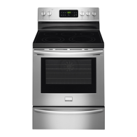
Physical dimensions and clearances for the 36-inch dual fuel range.

Installer and Consumer Guidance

Important notes for installers and consumers regarding installation and use.

Safety Compliance and Optional Items

Adherence to codes and available optional accessories for the range.

Installation Safety and Identification

General Installation Safety Precautions

Covers tipping prevention, floor protection, air flow, and child safety.

Massachusetts Installation Specifics

Special requirements for gas installation in Massachusetts.

Appliance Identification Location

Location of the model and serial number plate on the appliance.

Electrical Connections and Power

USA Power Supply Cord Kit

Guidelines for connecting a power supply cord kit in the United States.

Canadian Factory Power Cord

Information for ranges with factory-connected power cords in Canada.

Electrical Outlet Location

Suggested placement for junction boxes or wall receptacles.

Electrical Shock Hazard Warning

Critical warnings about grounding and electrical safety.

Range Electrical Wiring

Three-Conductor Wire Connection

Detailed steps for connecting a 3-conductor power supply cord.

Electrical Connection Safety Risks

Warnings about potential fire or shock from incorrect electrical connections.

Advanced Electrical Wiring and Grounding

Four-Conductor Connection (Mobile Homes)

Procedures for connecting a 4-conductor cord, especially for mobile homes.

Direct Electrical Connection Methods

Connecting the appliance directly to circuit breaker or junction box.

Wiring Material Warnings

Precautions regarding aluminum wiring and proper connectors.

Grounding Wire Restrictions

Rules and limitations for grounding through neutral wires.

Range Placement and Electrical Grounding

Four-Wire Grounding Junction Box

Connecting a 4-wire cable to a grounded junction box.

Range Placement Guidelines

Advice on positioning the range and avoiding heat damage to cabinets.

Excessive Weight Hazard Warning

Safety caution for moving and installing the heavy appliance.

Gas Supply Installation and Connection

Gas Supply Pressure and Regulator

Specifications for natural gas and LP/Propane pressure and regulator settings.

Connecting to Pressure Regulator

Step-by-step guide to assemble the flexible gas connector.

Gas Leak Detection Procedures

Methods for checking gas connections for leaks using a manometer or leak detector.

Gas Conversion, Servicing, and Leveling

LP/Propane Gas Conversion Process

Instructions for converting the appliance from natural gas to LP/Propane.

Appliance Servicing and Cleaning

Procedures for safely moving the range for maintenance or cleaning.

Leveling the Range for Stability

How to adjust leveling legs to ensure the range is stable and level.

Operation Checks and Burner Adjustments

Burner Components and Igniter Check

Verifying burner assembly and electronic igniter function.

Regular Burner Low Flame Adjustment

How to adjust the minimum flame setting on regular surface burners.

Oven Operation and Service Preparation

Dual Burner Low Flame Adjustment

Adjusting the minimum flame setting for dual surface burners.

Oven Element and Function Checks

Verifying the operation of oven heating elements and controls.

Preparing for Service Calls

Checklist and tips to save time and expense before calling for service.

Anti-Tip Bracket Installation

Anti-Tip Safety Warning and Importance

Critical warning about securing the range to prevent tipping and serious injury.

Required Tools for Bracket Installation

List of tools needed for proper installation of the anti-tip bracket.

Anti-Tip Bracket Installation Steps

Detailed instructions for physically installing the anti-tip bracket to the floor.

Related product manuals