SOI 12.06 FV 26/43 599 37 42-75
TEST PROCEDURES
PROCEDURE
LETTER
COMPONENT TEST
2. Control Panel
The following symptoms indicate a defective control unit. Before replace the control
unit, perform the Jog and Switch unit test (Procedure N) to determine if control unit is
faulty.
2-1.In connection with buttons.
a) When touching the buttons, a certain group of buttons do not produce a signal.
b) When touching the buttons, no buttons produce a signal.
2-2.In connection with indicators.
a) At a certain digit, all or some segments do not light up.
b) At a certain digit, brightness is low.
c) Only one indicator does not light up.
d) The corresponding segments of all digits do not light up; or they continue to light
up.
e) Wrong figure appears.
f) A certain group of indicators do not light up.
g) The figure of all digits flicker.
N
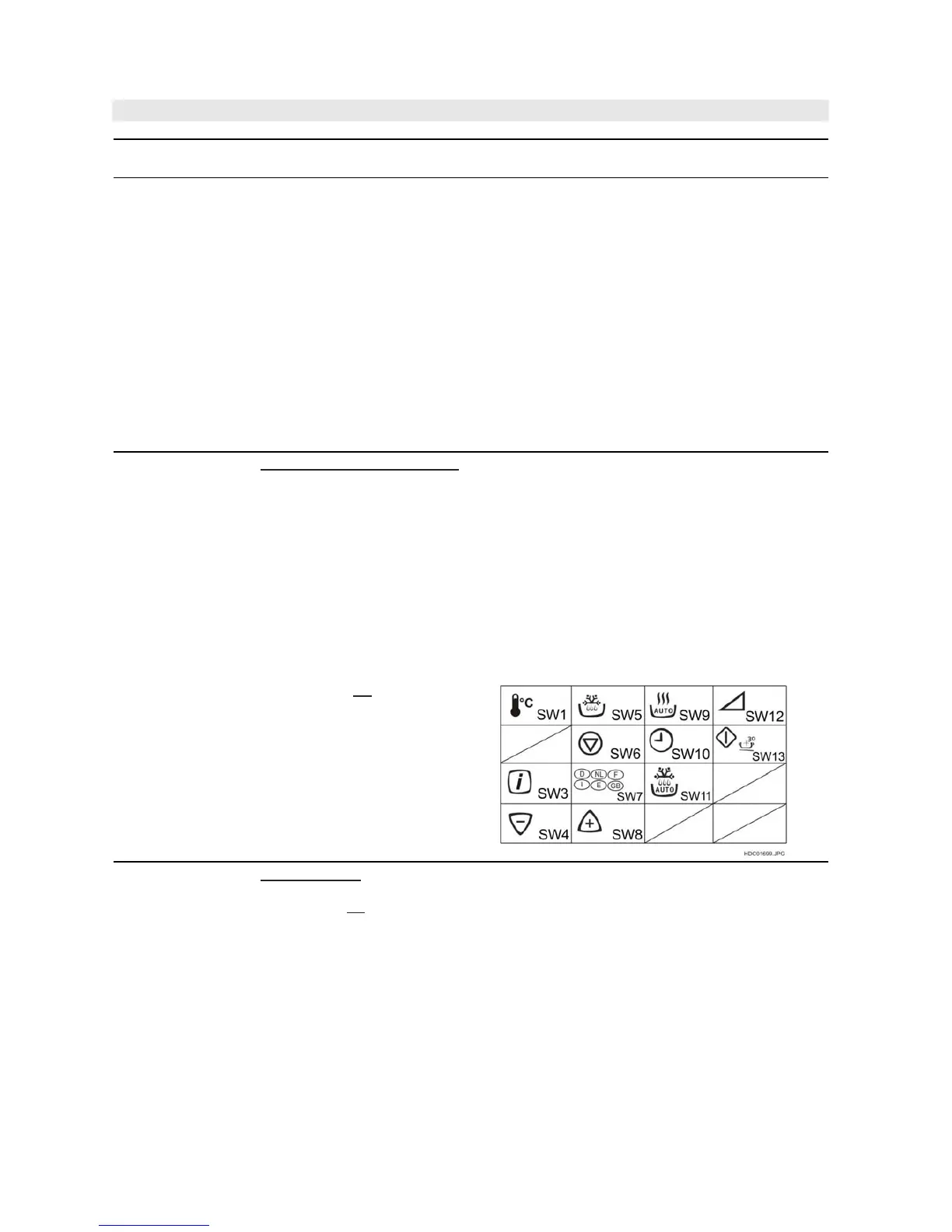
KEY AND JOG UNIT TEST
If the display fails to clear when the STOP pad is depressed, first verify the flat ribbon
cable is marking good contact, verify that the door sensing switch (stop switch) operates
properly; that is the contacts are closed when the door is closed and open when the door is
open. If the door sensing switch (stop switch) is good, disconnect the flat ribbon cable that
connects the key unit to the control unit and make sure the door sensing switch is closed
(either close the door or short the door sensing switch
connecter). Use the Key unit matrix indicated on the control panel schematic and place a
jumper wire between the pins that correspond to the STOP pad marking momentary
contact. If the control unit responds by clearing with a beep the key unit is faulty and must
be replaced. If the control unit does not respond, it is faulty and must be replaced. If a
specific pad does not respond, the above method may be used (after clearing the control
unit) to determine if the control unit or key pad is at fault.
CARRY OUT 4R CHECKS
O
RELAY TEST
CARRY OUT 3D CHECKS
Remove the outer case and check voltage between Pin Nos. 1 and 3 of the 4 pin
connector (E) on the
control unit with an A.C. voltmeter.
The meter should indicate 230 volts, if not check oven circuit.
Relay Test
Check voltage at the relay coil with a D.C. voltmeter during the microwave cooking
operation, grill operation, convection operation or dual operation.