SOI 12.06 FV 37/43 599 37 42-75
COMPONENT REPLACEMENT AND ADJUSTMENT PROCEDURE
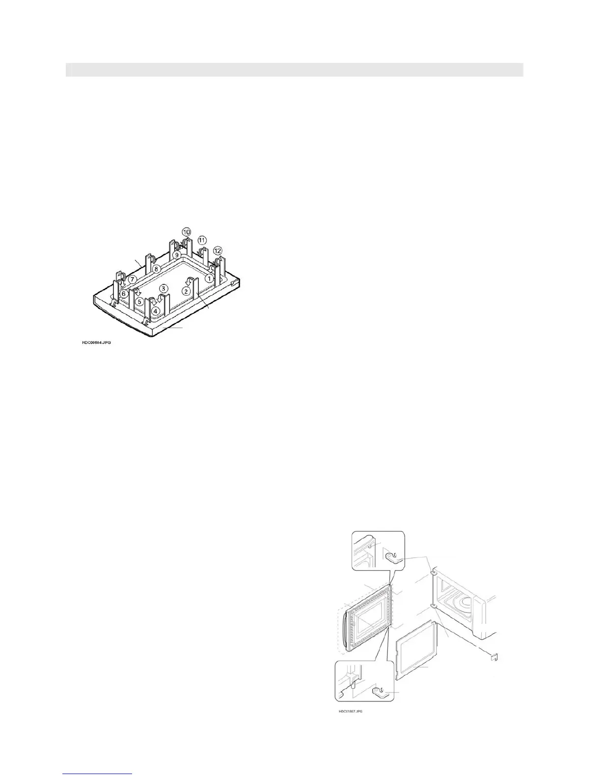
DOOR REPLACEMENT
REMOVAL
1. Disconnect the oven from the power supply.
2. Push the door slightly.
3. Remove the door stopper from the choke cover.
4. Lift the door upwards.
5. Now, door assembly is free from oven cavity.
6. Insert an putty knife (thickness of about 0.5mm) into
the gap between the choke cover and door frame as
shown in Figure C-7 to free engaging parts.
8. Now choke cover is free.
9. Release choke cover from door panel.
Figure C-7. Door Disassembly.
DOOR PANEL
10. Remove the eight (8) screws holding the door panel
to the door frame.
11. Now, door panel is free.
CAUTION: DO NOT DEFORM OR WARP THE TEETH
OF COMB OF THE DOOR PANEL TO
PREVENT MICROWAVE RADIATION
EMISSION FROM THE DOOR LATCH
HEAD AND SPRING
12. Slide latch head upward and remove it from door
frame with releasing latch spring from door frame
and latch head.
13. Now, latch head and latch spring are free.
DOOR HANDLE
14. Remove the two (2) screws holding the door handle
to the door frame.
15. Remove the door handle from the door frame.
RE-INSTALL
1. Re-install the door handle to the door frame as
follows.
a) Insert the door handle to the door frame.
b) Hold the door handle to the door frame with the
two (2) screws.
2. Re-install the latch spring to the latch head.
Re-install the latch spring to the door frame.
Re-install latch head to door frame.
3. Re-install door panel to door frame.
4. Hold the door panel to the door frame with
eight (8) screws.
5. Re-install choke cover to door panel by clipping
into position.
6. Locate door panel hinge pins into cavity hinge
location holes.
7. Re-install the door stopper to the chock cover.
Note: After any service to the door;
(A) Make sure that the monitor switch,
monitored latch switch and stop switch are
operating properly. (Refer to chapter "Test
Procedures".).
(B) An approved microwave survey meter
should be used to assure compliance with
proper microwave radiation emission
limitation standards.
(Refer to Microwave Measurement
Procedure.)
After any service, make sure of the following :
1. Door latch heads smoothly catch latch hook
through latch holes and that latch head goes
through centre of latch hole.
2. Deviation of door alignment from horizontal line of
cavity face plate is to be less than 1.0mm.
3. Door is positioned with its face pressed toward
cavity face plate.
4. Check for microwave leakage around door with
an approved microwave survey meter. (Refer to
Microwave Measurement Procedure.)
Note: The door on a microwave oven is designed to
act as an electronic seal preventing the
leakage of microwave energy from oven cavity
during cook cycle. This function does not
require that door be air-tight, moisture
(condensation)-tight or light-tight. Therefore,
occasional appearance of moisture, light or
sensing of gentle warm air movement around
oven door is not abnormal and do not of
themselves, indicate a leakage of microwave
energy from oven cavity.
Figure C-8. Door Replacement
Choke Cover
Putty Knife
Door Frame
PIN
UPPER
OVEN HINGE
DOOR SUB
ASSEMBLY
DOOR
PANEL
SLIT CHOCHE
CHOKE COVER
LOWER
LOWER
OVEN HINGE
OVEN HINGE
DOOR
STOPPER
PIN