Do you have a question about the Electrolux MC2660E (EU) and is the answer not in the manual?
Safety guidelines for personnel regarding microwave energy exposure.
Recommendations for service engineers studying the manual for customer service.
Essential checks before operating the oven to ensure safety.
Details on power requirements, output, dimensions, and cavity size.
Explains control system, clock settings, and microwave power levels.
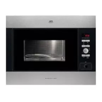
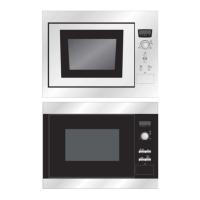
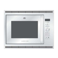
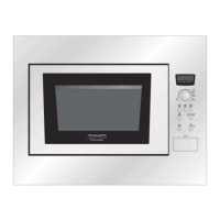
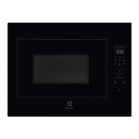
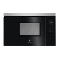
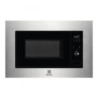
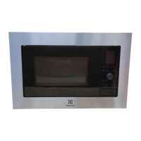
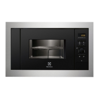
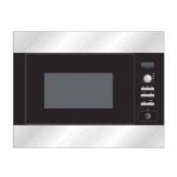
Labels external oven parts and the turntable support system.
Displays and explains control panels for MC2660E, ZM266ST, QN4040, JMW2061, EM2612.
Describes switch states and component operation in off and cooking modes.
Details the time ratios for different microwave power settings.
Explains door open, latch, monitor, and stop switches.
Details thermal cut-outs, turntable motor, fan motor, and noise filter.
Lists common problems, causes, and references test procedures for diagnosis.
Procedures for testing magnetron continuity and transformer windings.
Methods for testing switches, thermal cut-outs, and blown fuses.
Procedures for testing noise filter, motor windings, and control panel units.
Outlines control unit, LSI, power source, and indicator circuit functions.
Guidelines for handling CMOS LSI and preventing static electricity damage.
Steps and precautions for servicing the touch control panel.
Instructions for removing oven outer case and HV components.
Procedures for removing magnetron, transformer, control panel, and turntable motor.
Steps for replacing fan motor, oven lamp, and power supply cord.
Procedures for adjusting door switches and disassembling the door.
Method for testing microwave radiation emission compliance.
Quick reference for component values and data.
Precautions and best practices for electrical wiring.
Electrical circuit diagrams for oven operation states.
Visual representation of component connections and wiring.
| Brand | Electrolux |
|---|---|
| Model | MC2660E (EU) |
| Category | Microwave Oven |
| Language | English |