SOI 05.06 FV 19/34 599 36 78-44
TEST PROCEDURES
PROCEDURE
LETTER
COMPONENT TEST
H
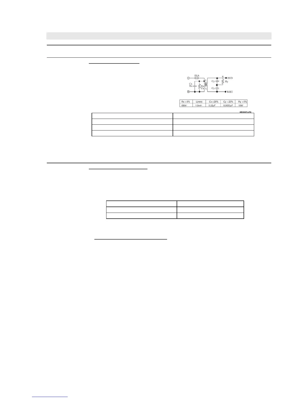
NOISE FILTER TEST
CARRY OUT 3D CHECKS
Disconnect the leads from the
terminals of the noise filter.
Using an ohmmeter, check between
the terminals as described in the
following table.
MEASURING POINTS INDICATION OF OHMMETER
Between N and L Open circuit
Between terminal N and WHITE Short circuit
Between terminal L and RED Short circuit
If Incorrect readings are obtained, replace the noise filter unit.
CARRY OUT 4R CHECKS
I
MOTOR WINDING TEST
CARRY OUT 3D CHECKS.
Disconnect the leads from the motor. Using an ohmmeter, check the
resistance between the two terminals as described in the table below.
Table: Resistance of Motor
Motors Resistance
Fan motor
Approximately 290 Ω
Turntable motor
Approximately 12 - 15 kΩ
If incorrect readings are obtained, replace the motor.
CARRY OUT 4R CHECKS.
LIVE TEST FOR MOTOR WINDING
CAUTION: The following procedure requires the oven to be connected
to the supply and should only be used if the relevant "cold"
checks for the motor under test are inconclusive.
1. CARRY OUT 3D CHECKS.
2. Disconnect the leads from the primary of the high voltage transformer. Make
sure that the leads remain isolated from other oven components and
chassis (Use insulation tape if necessary).
3. Connect the voltmeter, set to 250V AC, across the motor terminals. (Refer
to the relevant motor test procedure or pictorial diagram for the correct
terminal numbers.)
4. Arrange the meter in a position where it can be read during the test.
(Do not touch the meter, meter leads or oven circuitry while the oven is
active.)
5. Close the oven door.
6. Set the power level to 900W and set the relevant timer for about three (3)
minutes.
7. Note the reading on the meter and carefully observe the motor under test to
see if it is turning.
8. CARRY OUT 3D CHECKS.
9. Remove the test meter leads.
10.Reconnect the leads to the primary of the high voltage transformer.
If a reading of the line voltage was obtained (step 7) but the motor was not
turning then it is faulty and should be replaced. If the meter indicated that the
no supply was present then the winding to the motor should be O.K.. Other
circuit checks should be made, i.e. relays, switches.