SOI 05.06 FV 29/34 599 36 78-44
COMPONENT REPLACEMENT AND ADJUSTMENT PROCEDURE
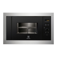
MONITORED LATCH SWITCH, MONITOR SWITCH AND STOP SWITCH REMOVAL
1. CARRY OUT 3D CHECKS.
2. Remove the control panel assembly
referring to "CONTROL PANEL
ASSEMBLY REMOVAL".
3. Disconnect the all leads from the
switches.
4. Remove the two (2) screws holding the
latch hook to the oven cavity.
5. Remove the latch hook.
6. Push the retaining tab slightly and remove
the switch.
Figure C-2. Latch Switches
MONITORED LATCH SWITCH, MONITOR SWITCH AND STOP
SWITCH ADJUSTMENT
If the monitored latch switch, stop switch and
monitor switch do not operate properly due
to a mis-adjustment, the following adjustment
should be made.
1. CARRY OUT 3D CHECKS.
2. Loosen the two (2) screws holding the
latch hook to the oven cavity front flange.
3. With the door closed, adjust the latch
hook by moving it back and forward, or up
and down. In and out play of the door
allowed by the latch hook should be less
than 0.5mm. The horizontal position of
the latch hook should be placed where the
monitor switch has activated with the door
closed. The vertical position of the latch
hook should be placed where the
monitored latch switch and stop switch
have activated with the door closed.
4. Secure the screws firmly.
5. Make sure of the monitored latch switch,
stop switch and monitored switch
operation. If those switches have not
activated with the door closed, repeat step
1 - 4.
After adjustment, make sure of following:
1. In and out play of door remains less than
0.5mm when patches position. First
check latch hook position, pushing and
pulling upper position of the door toward
the oven face. The results (play of the
door) should be less then 0.5mm.
2. The contacts (COM-NO) of monitored latch switch
and stop switch interrupt the circuit before the door
can be opened.
3. The contacts (COM-NC) of the monitor switch
close when door is opened.
4. Re-install outer case and check for microwave
leakage around the door with an approved
microwave survey meter. (Refer to Microwave
Measurement procedure.)
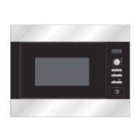
Figure C-3. Latch Switch Adjustments
MONITOR SWITCH
MONITORRED
LATCH SWITCH
STOP SWITCH
TAB
TAB
TAB
DOOR
LATCH HOOK
MONITOR
SWITCH (SW2)
MONITORED
LATCH
SWITCH (SW1)
LATCH
HEADS
STOP
SWITCH
(SW3)
OPEN LEVER
DOOR OPEN BUTTON