4:1
438 9143-01/05
5358
1
A
C
E
B
D
G
F
H
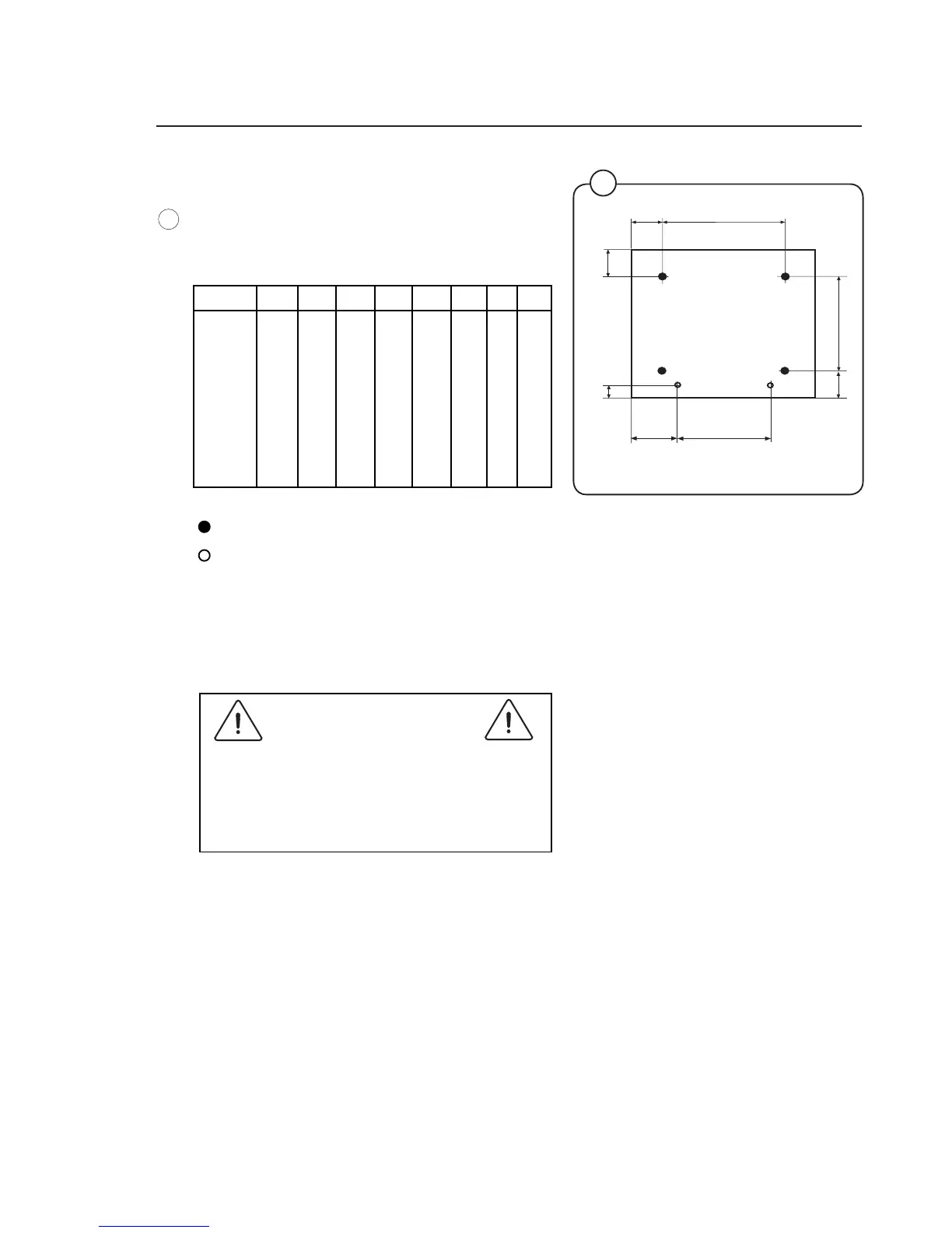
= position of feet
= drilling points for expander bolts
• The
machine shall be lifted in the bottom
frame.
• Place the machine over the two drilled holes.
• Check
that the machine is placed in level.
Adjust with the feet.
It is of utmost importance that the machine
is placed in level, from side to side as well
as front to rear. If the machine is not pro-
perly leveled, it may result in out-of-balance
without a real out of balance in the drum.
• Insert the expansion bolts supplied in the
holes drilled in the floor. Fit the washers and
nuts, and tighten well.
Mechanical installation
• Mark and drill 2 holes (ø 8 mm) about 40 mm
deep (W365-W3105) and ø 10 mm and 50 mm
deep (W3130-W3240) in the positions shown.
Installation
Fig.
1
Front
A B C D E F G H
W365H 495 460 110 130 375 170 40 100
W375H 495 460
110 130 375 170 40 100
W3105H 575 465 130 140 455 185 35 95
W3
130H 635 490 135 175 515 195 60 110
W3180H 715 545 125 205 595 185 60 115
W3240H 790 6
15 115 180 670 175 60 115
W3300H 903 835 60 180 670 175 60 75
 Loading...