Do you have a question about the Electrolux Washing machines and is the answer not in the manual?
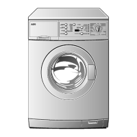
Describes manual scope, model EWM2000EVO, SIGMA LCD version, and production details.
Emphasizes qualified service engineers and unplugging the appliance before touching internal components.
Lists key technical specifications including voltage, frequency, motor, and system types.
Describes the control panel version with left selector and incorporated ON/OFF switch.
Mentions the 6 buttons and 1 LED present on the control/display board.
Explains the content displayed on the LCD for current selection, status, temperature, spin, and options.
Identifies control panel elements like buttons and describes the language selection process.
Describes how to adjust the programme temperature and spin speed.
Details how to select and confirm options using the control buttons.
Covers Extra Rinses, Time Saving, and Delayed Start functionalities.
Explains Prewash, Stains, Easy Iron, Energy Saving, and Setup options.
Describes how to exit programme selection and use the Start/Pause function.
Covers menu access, memory saving, sound, rinse, and language settings.
Details how to set the clock, adjust contrast, and control display brightness.
Covers programme parameters, selector operation, and start/pause functions.
Lists standard wash programmes with temperatures, rinses, and spin speeds.
Shows which washing options are compatible with different programmes.
Describes Night Cycle, Rinse-Hold, Pre-wash, Soak, and Stains options.
Explains Short, Very Short, Intensive, and other performance-related options.
Details Economy/Energy, Sensitive, Half Load, Reduced Spin, and No Spin options.
Explains Extra Rinse, Bleach, and Easy-Iron options.
Covers spin speed adjustment and time reduction (Quick) functionality.
Details temperature adjustment and how to exclude the buzzer.
Table showing the number of rinses for various selected options.
Notes on Half Load and Turbidity sensor impact on rinses.
Details the sequence of operations for Cotton/Linen programmes at various temperatures.
Details the phases for cotton rinse programmes with two or three rinses.
Details the sequence of operations for Cotton/Linen energy label programmes.
Details the phases for energy label programmes with two rinses.
Details the phases for energy label programmes with three rinses.
Details the sequence of operations for synthetics programmes at various temperatures.
Details the phases for synthetics rinse programmes (1st, 2nd, Last).
Details the sequence of operations for delicate fabrics programmes.
Details the sequence of operations for wool programmes.
Details the sequence of operations for hand wash programmes.
Details the sequence of operations for the automatic wash programme.
Describes Delicate, Normal, Vigorous, Wool, and Hand Wash drum movements.
Details spin phase drum movements for Cotton/Linen and Synthetics programmes.
Details final spin movements for Delicates, Wool, Easy Iron, and CSR programmes.
Lists different water fill level types and their descriptions for various programme groups.
Describes the main PCB and control/display board of the EWM2000 EVO system.
Details main board functions and the control system's memory structure.
Explains the breakdown of microprocessor memory into ROM, RAM, and EEPROM.
Explains how the analogic pressure switch controls water level in the tub.
Details the settings for anti-boiling and anti-overflow water levels.
Describes 3 and 4 compartment detergent dispensers and solenoid valves.
Explains the function of the third pressure switch level as an anti-overflow safety device.
Describes how the main board is powered and connected to the programme selector.
Explains the operation principle of the voltmetric door interlock with PTC.
Describes the function of the pilot lamp indicating the door lock status.
Explains the operation principle of the instantaneous door interlock.
Lists conditions for door release and details the automatic release device.
Describes solenoid valves, powering, and water level detection.
Identifies the components of the flow meter assembly.
Explains how the flow meter works and describes potential malfunctions.
Explains how the drain and recirculation pumps are controlled by the PCB.
Describes leak detection, drain activation, and the float switch mechanism.
Describes the heating element and the NTC temperature sensor.
Lists NTC sensor resistance values at different temperatures.
Explains how the turbidity sensor works and its role in rinse cycle optimization.
Details motor parts, power supply, relays, and speed control mechanisms.
Explains the logic of the anti-foam control system using pressure switches.
Details the dynamic control procedure for unbalanced loads and its phases.
Describes the conditions under which the FUCS balancing phase ends.
Illustrates balancing within intervals and describes failure scenarios.
Explains demo mode operation, limitations, and how to enter/exit.
Describes how to enter and exit the diagnostics system.
Provides an overview of the phases performed during the diagnostics test.
Details each diagnostic phase, component action, operating conditions, and checks.
Checks the LCD display board's symbols, segments, and LED lights.
Details checking programme selector contacts and their corresponding coding.
Lists user-displayed alarms and conditions for door opening during alarms.
Provides notes on configuration alarms and power supply issues.
Explains how to quickly view the last alarm code on the LCD.
Describes the procedure to cancel the last alarm via diagnostics mode.
Details alarm codes, possible faults, and actions for the main electronic board.
Continues the table of alarm codes, possible faults, and actions for the main board.
Details alarm codes, possible faults, and actions for the LCD display board.
Explains how to access and display the appliance's operating time on the LCD.
Details the steps for accessing and removing the control panel assembly.
Provides steps for removing the LCD display board and replacing the programme selector.
Steps for control panel reassembly and accessing Flow Meter/Aqua Control.
Provides steps for removing and installing the turbidity sensor.
Presents the basic circuit diagram of the appliance with sensors.
Lists electric components and their corresponding main board connections for the circuit diagram.
| Brand | Electrolux |
|---|---|
| Model | Washing machines |
| Category | Washer |
| Language | English |