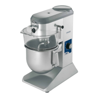
2.2 INSTALLATION
• The 20/30 litre mixers are oor-standing only.
• To chock or level the beater:
- Remove the foot end piece before adjusting.
- Screw with a screwdriver so that the adjustable pad makes
contact.
- Check it is stable by running the beater at high speed with its
beater. Where necessary, the adjustment can be ne-tuned
with the machine running.
- Ret the plug.
•
To x the beater to the oor: x by the rear feet
- Remove the end pieces from the 2 rear feet.
- Mark the 2 holes to be drilled (Ø8 max. screw, min. length 80,
plugs not supplied).
Note : It is also possible to x to the oor by the front feet,
by removing the adjustable pad.
• The 20 litre table mixers can be installed on:
- perfectly stable, non resonant support (unit, table, etc) of height
between 350 and 500 mm.
- an optional stainless steel table with storage shelf.
• To install, proceed as follows:
- Remove the adjustable pads from the front feet.
- Line up the 4 feet xing holes on the mixer with those on the
table.
- Fix the mixer on the table using the screw set provided.
• To chock or make the table level:
- Unscrew the screws xing the pads (13 mm pipe wrench).
- Adjust the pad, then lock in position.
- Check for stability by running the mixer at high speed with its
paddle.
• To embed the table in the oor :
- Counter drill the pad xing holes (plugs and screws max ø 8,
length min 30, not supplied).
2.2a
2.2c
2.2b
2.1 DIMENSIONS - WEIGHT (for information only)
A Gross weight when packaged (kg)
B Net weight equipped (kg)
C Packaging dimensions (mm) L x W x H
D Machine dimensions: L x W x H (mm)
E Dimensions for beater bedding: E x E1 x E2 (mm)
Hp Accessories hub height (A models)
. Handling - Transport
- The beater is delivered xed to a wooden pallet.
- Use a forklift truck to remove it from the pallet, slipping the
forks beneath the feet.
If unloaded manually, take all necessary precautions to
ensure the appliance does not tip at all
2.3 ELECTRICAL CONNECTION
ATTENTION!!
Connection to the electrical power supply must be done according to proper professional practice by a qualied and authorised
person (see current standards and legislation in the country of installation).
If an adapter is used on the socket, a check must be made that the electrical characteristics of this adapter are not lower than
those of the machine.
Do not use multiple plugs
The AC power supply to the machine must comply with the following conditions (EN60204-1);
- Maximum voltage variation: ±10%
- Maximum frequency variation: ±1% on a continuous basis, ± 2% over short periods
ATTENTION: the electrical installation must comply (for design, creation and maintenance) with the legal and standard
requirements in the country where used.
- Check that the electric mains voltage, the value shown on the specication plate.
- The machine’s electrical power supply must be protected against voltage surges (short-circuits and excess voltages) by using
fuses or thermal relays of the appropriate gauge relative to the place of installation and machine specications – see the spe-
cications shown in column F of gure 2.3a
ATTENTION: Concerning protection against indirect contact (depending on the type of power supply provided and
connection of the exposed conductive parts to the equipotential protection circuit), refer to point 6.3.3 of EN 60204-1
(IEC 60204-1) with the use of protection devices for automatic shut-o of power in the event of an insulation fault with
a TN or TT, system, or for the IT system, with the use of a permanent insulation or dierentials controller for automatic
shut-o. The requirements of IEC 60364-4-41, 413.1 must apply for this protection.
For example: in a TT system, a dierential circuit breaker must be installed upline of the power supply, with a suitable
power cut-o (e.g.: 30 mA) on the earthing installation for the place where it is planned to install the machine.
ATTENTION: Failure to comply with these instructions means the customer runs the risk of machine failure and/or acci-
dents due to direct or indirect contacts.
XBM20/30 GB 09 2023 2