TC M Temperature Controller User Manual V1.08
Electron Dynamics Ltd page
4
Consult Electron Dynamics for possibilities
3.5 Other temperature sensors
These are possible please consult Electron Dynamics for advice.
3.6 TEC connection
Connect to J3 noting polarity, actual drive polarity can be configured by software
3.7 Power connection
Power should be applied to J2
3.8 Alarm output
This is provided from J4, this is active when low.
3.9 Inhibit
This is provide from J1 and inhibits the drive when the pins of j1 are connected together.
For multiple uses the TCM temperature controller can be made to inhibit control of other TCM controllers by
its alarm output indicated by LED2. To achieve this, the alarm output will need to be daisy chained to the
inhibit switch of the respective controller.
3.10 USB
This is provided from J5.
Note this operates as a virtual COM port
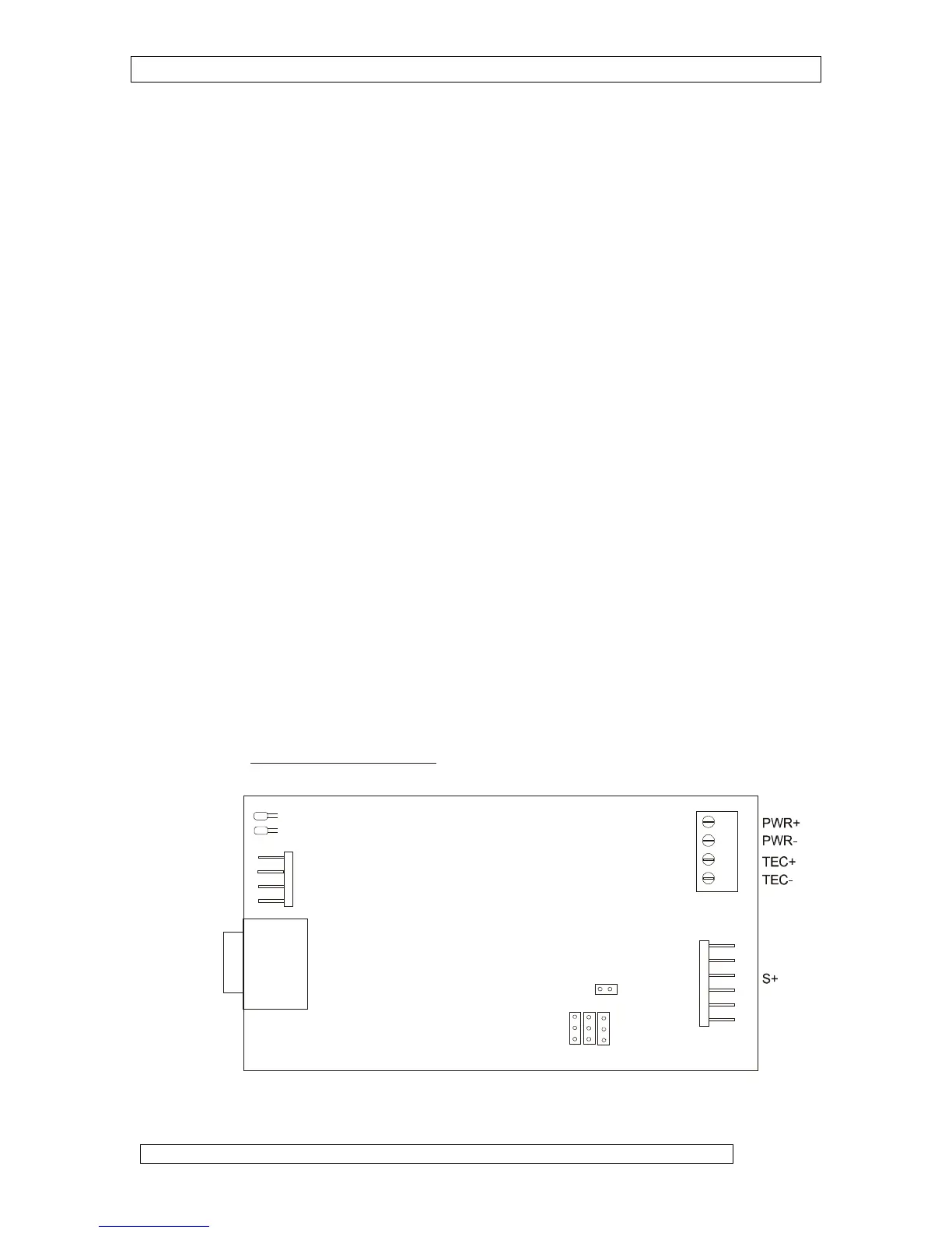
3.11 PCB Connector / Link positions
+
1 1
1
D connector
Connector
Alarm O/P
Temp Alarm LED
Temp OK LED
Inhibit I/P