This document describes the EA-PS 10000 4U series of programmable DC power supplies from EA Elektro-Automatik, designed for industrial test applications requiring high power, current, or voltage. All models in this series have a rated power of 30 kW and offer a broad spectrum of applications.
Function Description
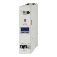
The EA-PS 10000 4U series are electronic high-performance power supplies that can operate as variable voltage and current sources or sinks. They are intended for installation and operation in suitable equipment, such as a 19" rack, with a rigid, non-retractable AC supply connection. Typical applications include DC power supply to various users, including battery charging and testing, and replacing ohmic resistors with adjustable electronic DC loads.
For remote control, the devices come standard with USB and Ethernet ports on the rear, as well as a galvanically isolated analog interface. Optional plug-in interface modules (e.g., RS232, Profibus, ProfiNet, ModBus TCP, CAN, CANopen, EtherCAT) can be added for connection to standard industrial buses.
The devices support parallel connection in a "Share bus" operation for constant current sharing, and a true master-slave connection that totals all actual values. This allows up to 64 units to be combined into a single system with a total power of up to 1920 kW. Water-cooled versions are available, typically configured in cabinet systems with a complete water cooling distribution.
The device's internal control circuits regulate voltage, current, and power to adjusted values, maintaining them constant where possible. Different operating modes include:
- Voltage Regulation (CV): Maintains constant DC output voltage until output current or power reaches an adjusted limit, then automatically switches to constant current or constant power operation.
- Current Regulation (CC): Maintains constant DC output current until output voltage or power reaches an adjusted limit, then automatically switches to constant voltage or constant power operation.
- Power Regulation (CP): Keeps DC output power constant if the current flowing to the load in relation to the output voltage and load resistance reaches the adjusted value. This operates on an auto-range principle, allowing higher current at lower voltages and vice versa to maintain constant power.
- Internal Resistance Regulation (CR): Simulates a virtual internal resistor in series with the load, causing a voltage drop. This mode works in CV, CC, or CP modes, with the actual output voltage differing from the adjusted voltage.
Important Technical Specifications
- AC Input: 208 V / 380 V / 400 V / 480 V ±10%, 3ph AC (208 V 3ph AC with Derating to 18 kW), 45-66 Hz, Power factor >0.99, Leakage current <10 mA.
- DC Output Static:
- Load regulation CV: ≤0.05% FS (0-100% load, constant input voltage and temperature)
- Line regulation CV: ≤0.01% FS (208 V - 480 V AC ±10% input voltage, constant load and temperature)
- Stability CV: ≤0.02% FS (Over 8hrs interval following 30 minutes warm-up, constant input voltage, load and temperature)
- Temperature coefficient CV: ≤30ppm/°C (Following 30 minutes warm up)
- Load regulation CC: ≤0.1% FS (0-100% load, constant input voltage and temperature)
- Line regulation CC: ≤0.01% FS (208 V - 480 V AC ±10% input voltage, constant load and temperature)
- Stability CC: ≤0.02% FS (Over 8hrs interval following 30 minutes warm-up, constant input voltage, load and temperature)
- Temperature coefficient CC: ≤50ppm/°C (Following 30 minutes warm up)
- Load regulation CP: ≤0.3% FS (0-100% load, constant input voltage and temperature)
- Load regulation CR: ≤0.3% FS + 0.1% FS current (0 - 100% load, constant input voltage and temperature)
- Protective Functions:
- OVP (Overvoltage protection): Adjustable, 0 - 110% UNominal
- OCP (Overcurrent protection): Adjustable, 0 - 110% INominal
- OPP (Overpower protection): Adjustable, 0 - 110% PNominal
- OT (Overtemperature protection): Output shuts down in case of insufficient cooling.
- DC Output Dynamic: Rise time 10-90% CV <20 ms, Fall time 90-10% CV <20 ms, Rise time 10-90% CC <10 ms, Fall time 90-10% CC <10 ms.
- Display Accuracy: Voltage ≤0.05% FS, Current ≤0.1% FS.
- Insulation: AC Input to DC Output 3750 Vrms (1 Minute), creepage distance >8 mm.
- Interfaces Digital: Built-in galvanically isolated USB, Ethernet (100 MBit). Optional galvanically isolated CAN, CANopen, RS232, ModBus TCP, Profinet, Profibus, EtherCAT, Ethernet.
- Interfaces Analog: Built-in galvanically isolated 15-pole D-Sub, Signal range 0-10 V or 0-5 V (switchable).
- Environmental Conditions: Operating temperature 0-50 °C, Storage temperature -20-70 °C, Humidity ≤80% RH, non-condensing, Altitude ≤2000 m.
- Mechanical Construction: 19" x 4U x 668 mm, Weight 50.0 kg (110 Lb), Weight with water cooling 56.0 kg (126 Lb).
Usage Features
- Control Panel (HMI): Features a color TFT touchscreen with Gorilla Glass (5", 800x480pt, capacitive), two rotary knobs with pushbutton function, and one additional pushbutton. The touchscreen allows selection of set values, menus, and settings, and displays actual values and status. Rotary knobs adjust voltage, current, power, or resistance set values, with push functions to shift decimal positions.
- DC Output On/Off: A dedicated pushbutton with LED status display toggles the DC output.
- USB Host (Front Side): For connecting standard USB sticks to record measured data (logging) and load profiles. Supports FAT32 formatted sticks up to 32 GB.
- USB Port (Rear Side): USB-B port for communication with a PC and firmware updates. Installs as a virtual COM port.
- Analog Interface (Rear Side): 15-pole D-Sub socket for remote control via analog or digital signals. Input voltage range for set values and output voltage range for monitor values are switchable between 0-5 V and 0-10 V.
- Share BUS Connector: Two BNC sockets (50 Ω type) for parallel operation, balancing voltage across multiple units in CV mode.
- Master-Slave Bus: Two RJ45 sockets for connecting multiple identical devices via a digital bus (RS485) to create a master-slave system. Up to 64 units can be combined.
- Ethernet Port: RJ45 LAN/Ethernet port for remote control or monitoring via a web interface (HTTP) or TCP/IP access. Supports SCPI or ModBus RTU protocols.
- Adjustment Limits: Upper and lower limits for current and voltage, and upper limits for power and resistance, can be set to protect applications.
- User Profiles: Up to 5 user profiles can be saved and loaded, storing all settings and set values, including language.
- Logging: Device data can be recorded to a USB stick in CSV format. Logging can be started manually or automatically with DC output changes.
- Quick Menu: Provides quick access to frequently used features and modes.
- Graph: Visual depiction of temporal runs of actual voltage, current, and power values on the HMI.
Maintenance Features
- General Maintenance: The device requires no regular maintenance. Cleaning of internal fans may be needed depending on ambient conditions to ensure sufficient airflow and prevent overheating.
- Battery Replacement: The device contains a Lithium cell battery (CR2032) for buffering the internal real-time clock. Replacement can be done by qualified personnel while maintaining ESD precautions.
- Fault Finding/Diagnosis/Repair: In case of unexpected behavior or obvious defects, users should contact the supplier. Returns for checking or repair should include detailed fault descriptions and suitable transport packaging.
- Firmware Updates: Firmware for the control panel (HMI), communication unit (KE), and digital controller (DR) can be updated via the rear USB port using EA Power Control software. Updates are recommended only to eliminate existing bugs or utilize new features, as they carry a risk of making the device inoperable.
- Troubleshooting: The manual provides guidance on problem situations, possible hazards, and safety measures, such as connecting external sources with reversed polarity.