Do you have a question about the ElektroPhysik MiniTest 735 and is the answer not in the manual?
Guide to inserting batteries and connecting the sensor for operation.
Instructions on how to power on the gauge and take initial readings.
Information on using alkaline and rechargeable batteries.
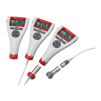
Explains SIDSP® technology and MiniTest 745 specific sensors.
Describes the initial screen and sensor/gauge identification upon power-on.
Overview of the main screen elements displayed during measurement.
Key considerations for accurate coating thickness measurement.
Describes essential settings before taking measurements.
Explains how readings are grouped into batches for data management.
Covers calibration preparation before taking measurements.
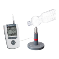
Instructions on how to take measurements using the sensor.
Details on taking readings by placing the sensor directly on the object.
General principles and important considerations for optimal calibration.
Overview of available calibration methods like factory, manual, and pre-set.
Details on manual calibration techniques: zero, two-point, multi-point.
Step-by-step guide for performing a zero calibration.
Procedure for calibrating using a zero point and one precision standard.
Method for multi-point calibration using zero and two precision standards.
Strategies for handling roughness influence in measurements.
Explains how surface roughness affects measurement results.
General instructions and remarks on performing calibration.
Key points for selecting and performing calibration methods.
Step-by-step guide for manual calibration of FN sensors.
Step-by-step guide to creating a new batch for measurements.
Instructions on how to select an existing batch to start a measurement series.
How to view statistical summaries of the measured data.
How to print out statistical values and transfer data to a PC.
Instructions on printing readings and statistics to a MiniPrint 7000.
Lists common error messages and their corresponding solutions.
Troubleshooting for sensor connection interruptions or failures.
Error when the gauge cannot establish a connection to the sensor.
Indicates a sensor problem requiring service contact.
Direct message indicating sensor failure and need for service.
| Measurement Range | 0 to 2000 µm |
|---|---|
| Measuring principle | Magnetic induction |
| Data storage | Up to 1000 readings |
| Interface | USB |
| Standards | ISO 2808, ASTM D7091 |
| Resolution | 0.1 µm |
| Display | LCD |
| Operating Temperature | 0 to 50 °C |
| Storage Temperature | -20 to +60 °C |
| Battery Life | Approx. 50 hours (alkaline batteries) |