Do you have a question about the Elenco Electronics M-2666K and is the answer not in the manual?
Lists the six assembly sections (A-F) for the multimeter kit.
Explains the A/D converter's role in processing signals and driving the LCD display.
Details the autozero, integrate, and read phases of the A/D conversion process.
Simplified diagram illustrating voltage measurement circuitry.
Simplified diagram illustrating current measurement circuitry.
Simplified diagram illustrating resistance measurement circuitry.
Diagrams and descriptions for hFE and capacitance measurement circuits.
Detailed block diagram and pinout for the ICL7106 IC.
Essential guidelines for successful multimeter assembly and component handling.
Visual and descriptive guide to good soldering techniques and common pitfalls.
Guides for identifying capacitor and resistor values using color codes and markings.
Exercise to familiarize users with reading 5-band resistor color codes.
Visual identification of parts for the meter display circuit assembly.
Instructions for mounting resistors, capacitors, and transistor T1.
Instructions for SW1, battery snap, and visual guides A-E.
Steps to assemble the LCD into its housing and perform initial tests.
Visual identification of parts for DC voltage and current circuits.
Instructions for mounting diodes, resistors, and VR1.
Steps to test the assembled DC voltage and current circuits.
Visual identification of parts for AC voltage and current circuits.
Instructions for mounting diodes, resistors, and capacitors.
Visual identification of parts for resistance and buzzer circuits.
Instructions for mounting resistors, capacitors, and buzzer.
Steps to test resistance, buzzer, and diode functions.
Visual identification of parts for capacitance and transistor circuits.
Instructions for mounting IC3, sockets, and diodes D6-D9.
Instructions for mounting resistors and capacitors for Section E.
Steps to test the capacitance measurement function of the multimeter.
Steps to test the transistor hFE measurement function.
List of parts for the final assembly stage.
Instructions for assembling the meter case, battery, and related components.
Steps to test AC voltage and current measurement functions.
Procedure to verify the operation of the main IC and reference voltage.
Troubleshooting steps for common issues in voltage, ohm, and AC voltage measurements.
Troubleshooting steps for amps, hFE, diode, and buzzer functions.
Specific steps to troubleshoot capacitance measurement issues.
Overview of display, operating conditions, power, and dimensions.
Detailed table of DC voltage ranges, resolutions, and accuracies.
Specifications for AC voltage and resistance measurement ranges and accuracy.
Specifications for DC/AC current and capacitance measurement ranges and accuracy.
Essential preparation and safety precautions before operating the meter.
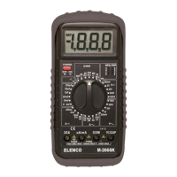
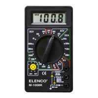
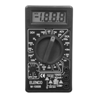
Identification and description of all controls and input jacks on the multimeter panel.
Step-by-step guide for measuring DC and AC voltages.
Step-by-step guide for measuring DC and AC currents.
Procedures for measuring resistance, testing diodes, and measuring transistor hFE.
Step-by-step guide for measuring capacitance.
Instructions for replacing the battery and fuse, including safety warnings.
Explanation of hazard, warning, caution, and voltage limit safety symbols.
Detailed schematic diagram of the entire multimeter circuit.
Questions to test understanding of multimeter operation and features.
| Display Type | LCD |
|---|---|
| Display Digits | 3.5 |
| Diode Test | Yes |
| Transistor Test | Yes |
| Continuity Buzzer | Yes |
| Square Wave Output | Yes |
| Continuity Test | Yes |
| Battery Type | 9V |
| DC Voltage | 200mV, 2V, 20V, 200V, 1000V |
| Resistance | 200Ω/2kΩ/20kΩ/200kΩ/2MΩ/20MΩ |
| Battery Test | 1.5V, 9V |
| Voltage Range (DC) | 200mV, 2V, 20V, 200V, 1000V |
| Resistance Range | 200Ω/2kΩ/20kΩ/200kΩ/2MΩ/20MΩ |