-3-
VOLTAGE MEASUREMENT
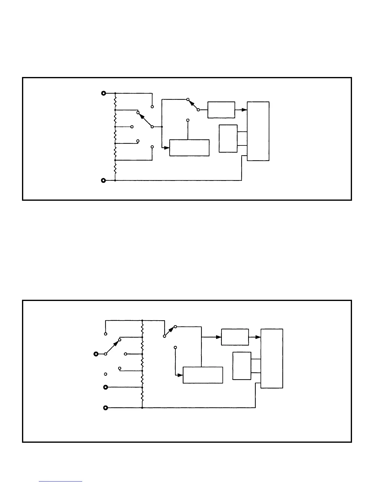
Figure 3 Simplified Voltage Measurement Diagram
Figure 4 Simplified Current Measurement Diagram
200mV
Volts
9MΩ
900kΩ
90kΩ
9kΩ
9Ω
Common
750V
200V
20V
2V
AC to DC
Converter
AC
DC
Low Pass
Filter
100mV
Ref
7106
200µA
A
900Ω
2mA
20mA
200mA
20A
COM
AC - DC
Converter
AC
DC
Low Pass
Filter
100mV
Ref
7106
Figure 3 shows a simplified diagram of the voltage
measurement function.
The input divider resistors add up 10MΩ with each
step being a division of 10. The divider output
should be within –0.199 to +0.199V or the overload
indicator will function. If the AC function is selected,
the divider output is AC coupled to a full wave
rectifier and the DC output is calibrated to equal the
rms level of the AC input.
Figure 4 shows a simplified diagram of the current
measurement positions.
Internal shunt resistors convert the current to
between –0.199 to +0.199V which is then
processed in the 7106 IC to light the appropriate
LCD segments. If the current is AC in nature, the
AC converter changes it to the equivalent DC value.
CURRENT MEASUREMENT
90Ω
9Ω
0.99Ω
0.01Ω
20A
 Loading...