This identification plate comes together with the orifice plate when you
order an orifice plate separately. Please make sure that your output
signals in the receiving end PLC, display, computer etc., are matched for the
new flow range. The micro switch might be necessary to adjust and we refer to
the section 3.4 for complete instruction on how to do this.
3.3 Change of Flow Direction
For GL/FA-models, first empty the pipe system so that it is un-pressurized
and has no flow!
At the time of ordering, you must specify in which direction the Flow Monitor
shall be mounted i.e. from which side is the flow entering the Pipe Section.
(Please refer to fig. 6 below for alternatives.) If, for some reason, the Flow Monitor
is ordered with the wrong flow direction, it is possible to change this in the field.
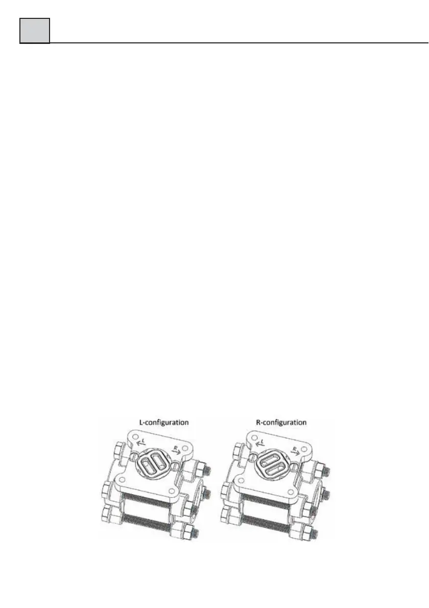
GL- and FA-models are delivered with a flow direction selector that can be used
for both directions.
To change the direction, loosen the four (4) hexagon screw, which hold the di-
aphragm housing to the Pipe Section. Remove the diaphragm housing and you
will see the flow direction selector (it might have attached itself to the bottom side
of the diaphragm housing). Replace the flow direction selector in the configuration
for your system (see fig. 7). There is a green marking indicating the flow
direction.
Please also remember to turn the red arrow mounted on the Pipe Section
(-GL and –FA models), to align with the new flow direction.
Fig. 7
 Loading...