The meter panel is covered by transparent cover moulded from UV ray-stabilised polycarbonate cover
providing protection from external mechanical factors and moisture.
The cover is fixed to the case by two sealed screws.
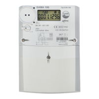
The liquid crystal display (LCD) is located in the frontal part of the meter. It allows the display of all
values stored in the memory, instantaneous values and parameters.
On the lower left, a display control photo sensor is located. In order to display specific information on
the display, a corresponding light signal must be transmitted to the photo sensor.
The D0 optical interface is located on the right side of the frontal part. The purpose of this interface is
data transfer between the meter and a portable computer or terminal and the meter parameterisation.