10
2 Designation
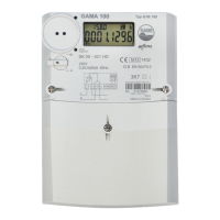
The static meter of direct connection GAMA 100 (G1B.xxx) is designated for measurement of
active or active and reactive electrical energy in alternate current networks. G1B meters can
measure active energy in both directions (+A and –A, as well as |A|) simultaneously and measure
reactive energy in directions (+R and -R), as well as in four quadrants (R1, R2, R3, R4)
simultaneously.
G1B.xxx meters can register maximum demand on daily and monthly bases, measure
instantaneous values as well as record load profile and event log.
Meters can be either single-rate or multi-rate. The rates are controlled by internal real-time clock.
G1B.xxx meters have S0 output(s) and optionally can have optical and electrical communication
interfaces for local and remote data transmission.
Meter G1B.xxx conforms to the following requirements of directives and standards:
- Directive 2004/22/EC of the European Parliament and of the Council of 31 March 2004 on
measuring instruments;
- Directive 2004/108/EC of the European Parliament and of the Council of 15 December 2004
on the approximation of the laws of the Member States relating to electromagnetic
compatibility and repealing Directive 89/336/EEC;
- EN 50470-3:2006 “Electricity metering equipment (a.c.) – Static meters for active energy
(class indexes A, B and C)”;
- EN 50470-1:2006 “Electricity metering equipment (a.c.) – General requirements, tests and
test conditions – Metering equipment (class indexes A, B and C)”;
- IEC 62053-21:2003 “Electricity metering equipment (a.c.) – Static meters for active energy
(classes 1 and 2)”;
- IEC 62053-23:2003 “Electricity metering equipment (a.c.) – Static meters for reactive
energy (classes 2 and 3)”;
- IEC 62052-11:2003 “Electricity metering equipment (a.c.) – General requirements, tests and
test conditions. Part 11: Metering equipment”;
- IEC 62052-21:2003 “Electricity metering equipment (a.c.) – General requirements, tests and
test conditions. Part 21: Tariff and load control equipment”;
- IEC 62054-21:2004 “Electricity metering equipment (a.c.) – Tariff and load control. Part 21:
Particular requirements for time switches”;
- IEC 62056-21:2002 “Electricity metering – Data exchange for meter reading, tariff and load
control. Part 21: Direct local data exchange”;
- IEC 529 “Degrees of protection provided by enclosures”
- IEC 61334-4-41 “Distribution automation using distribution line carrier systems – Part 4:
Data communication protocols – Distribution line message specification”
- IEC 62056-46 Data link layer using HDLC protocol;
- IEC 62056-53 DLMS/COSEM Application Layer;
- IEC 62056-61 DLMS/COSEM Obis code;
- IEC 62056-62 DLMS/COSEM Interface Classes.
- EN 13757-2:2005 Communication systems for and remote reading of meters - Part 2:
Physical and link layer;
- EN 13757-3:2005 Communication systems for and remote reading of meters - Part 3:
Dedicated application layer;
- EN 50065-1 Signalling on low-voltage electrical installations in the frequency range 3 kHz to
148,5 kHz -- Part 1: General requirements, frequency bands and electromagnetic
disturbances.
Note: Tables and Figures in this User manual may present measurement values and pulse outputs
in all possible energy and power directions. Actual number of measured values and pulse outputs
of a certain meter modification are indicated in meter passport.
 Loading...