6.6
Maintenance
for a few minutes.
Requirements
Strap wrench, new oil filter, O-ring, and clean cloth.
Maintenance
Disassembly of the existing oil filter:
Isolate the machine from the service line, vent
separator tank pressure, and allow the tank to cool for a
few minutes.
Hold the filter shell and rotate it counter clockwise using
the strap wrench.
Assembly of the new oil filter:
Ensure the O-ring of the filter is damage free.
Clean the seating surface with clean cotton.
Apply a thin film of compressor oil on the mating
surface of the O-ring.
Return the filter to its original position and rotate it
clockwise manually. After tightening, rotate it further by
hand for one and a half times.
Ensure no oil leaks from the mating surface.
6.1.2.6 Intake valve
Pre work:
Switch off the compressor and disconnect power supply
to the compressor.
Close the discharge end ball valve.
Release air oil tank pressure and allow the tank to cool
for a 10-minutes.
Requirements :
Soft cloth, grease, liquid cleaner, Allen keys, screw
driver, spanner, pressure gauge, service kit (if needed).
Procedure :
Function of NRV-flaps
Dismantling:
The valve must be completely dismantled from the
compressor. Then remove the bearing bolts (4), pin (5),
and the NRV-flap..
Cleaning:
Clean the interior of the housing with a liquid cleaner.
Wipe any Loctite residue from threads. Seat and sealing
areas must by no means be damaged.
Reassembly:
Wet a bearing bolt with Loctite 242 and screw it into the
thread. Install the NRV-flap or the NRV-flap and
counterweight in the housing according to the drawing.
Press the pin (4) through the bearing bores into the pre
-assembled bearing bolt. Wet the second screw with
Loctite 242 and screw it in. Lock both screws with 50 N-
m (30.87 lb-ft).
Function testing:
Check easy movement of the NRV-flap manually. It
must have slight axial play and not touch the housing.
1. Rotary drive unit
The valve must be completely dismantled from the
compressor. (Additionally, the control discs need to be
closed by using the pressure air signal as explained
before)
Turn out Tensilock screws (10) and remove the control
disc (1) (with a magnet). (Drain pressurized air.).
Remove the plastic plug (11). Turn out the MHT-nut
(15) and remove the 2 rings (13 & 14) below.
Attention: The spring (6) is pretensioned. When
screwing off the cover (8), therefore, press it by hand
onto the cover when turning out. Remove the sealing
ring (7), piston unit (9), spring (6), rod (12), and the
remaining 2 rings (16& 17).
Cleaning:
Wipe any residual loctite from the rod (12). Clean the
working area of the piston unit (9) with the liquid
cleaner and soft cloth. Grease the screw drive of the rod
(12) and piston working area with AUTOL TOP 2000.
Valves should not be opened when pressure is applied.
Suspended particulate matter should be less than 150spm
to achieve the specified consumable life. Guarantee
becomes void if the compressor is operated above its
intended pressure.
NOTE
The maintenance of following parts (valves) demands
highly skilled authorized personnel. So, it is recommended
that an ELGi service engineer does the maintenance.
NOTE
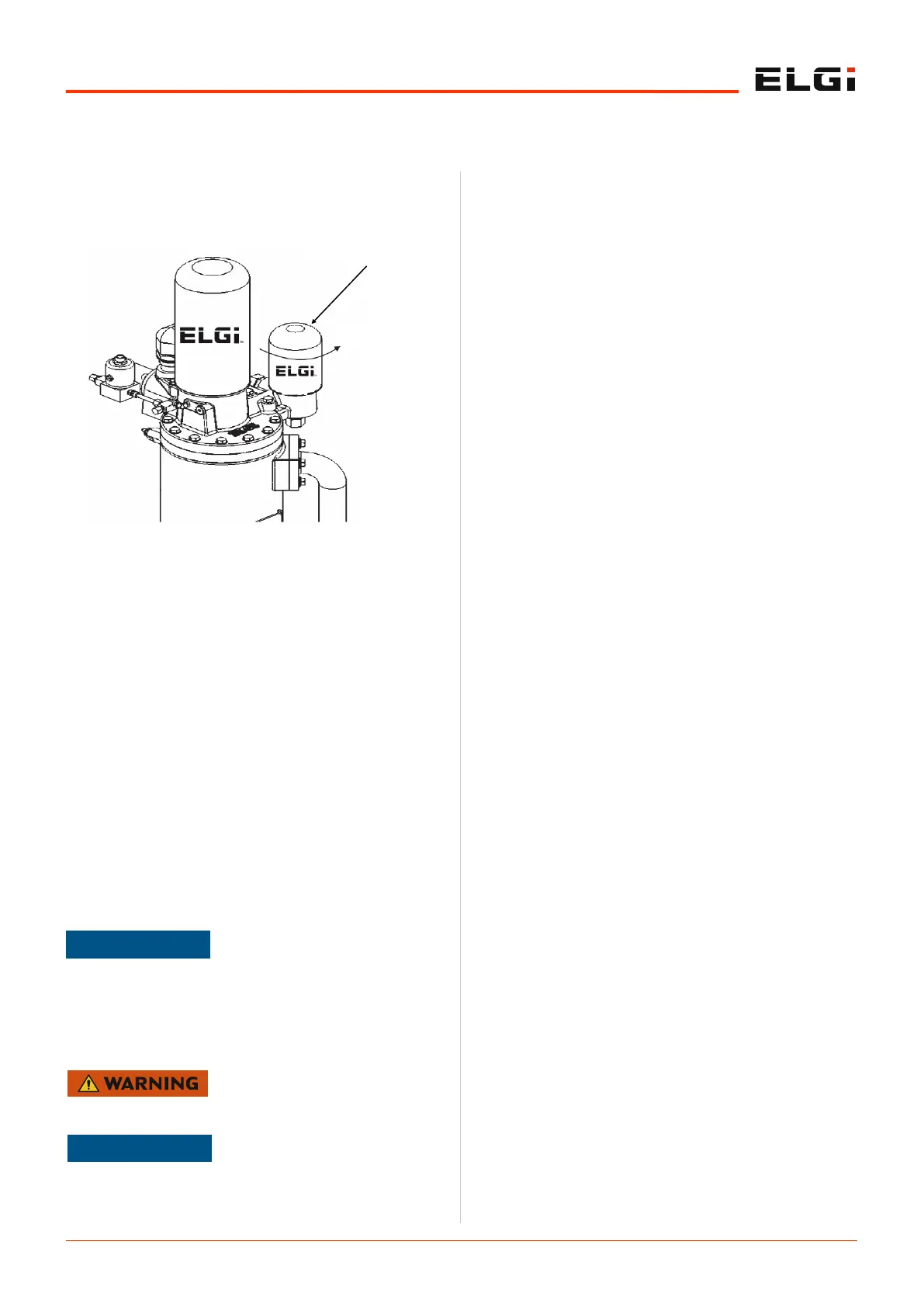
Figure 16. Oil filter
OIL FILTER SHELL
OPEN
 Loading...