Do you have a question about the Elitech ECS-2180neo and is the answer not in the manual?
Controls compressor based on indoor probe temperature, switching on at set point + differential and off at set point.
Defrost mode can be electric, hot gas, or off-cycle. It is interval timed and can be ended by a probe.
Fan operates continuously or with compressor. Features adjustable drip time and high temp stop point.
Sets the desired temperature for the controller. Has upper and lower limits.
Password for accessing the administrator menu. Default is 55.
Defines the temperature difference between switching on and off of the compressor.
Minimum time interval between compressor starts to prevent short cycling.
Minimum interval for the very first compressor start.
Allows calibration of the cabinet temperature sensor for accuracy.
Sets the minimum allowable temperature set point.
Sets the maximum allowable temperature set point.
Protects the compressor from frequent start/stop cycles.
Sets the minimum operational time for the compressor.
Selects the evaporator sensor, enabling or disabling it.
Calibrates the evaporator sensor to ensure accurate readings.
Determines how the defrost cycle is initiated, either by accumulated refrigeration time or natural time.
Sets the time interval between defrost cycles.
Configures what is displayed during defrost and related periods.
Sets the maximum duration for a defrost cycle.
Defrost cycle ends when this temperature is reached.
Allows time for condensate to drip off the coil after defrost.
Sets a delay before the cabinet temperature is displayed after defrost.
Sets a delay before the defrost cycle begins.
Selects the defrost method: electric heating or hot gas.
Configures how the fan operates in relation to the compressor and defrost cycles.
Delay before the fan starts after the controller is powered on.
Delay before the fan restarts after a defrost cycle.
Sets the minimum temperature at which the fan will operate.
Sets the maximum temperature at which the fan will operate.
Manages compressor operation during sensor failure for proportional control.
Sets the duration the compressor remains stopped during proportional control.
Sets the duration the compressor remains running during proportional control.
Enables or disables the buzzer alarm output.
Sets the lowest temperature threshold for a cabinet alarm.
Sets the highest temperature threshold for a cabinet alarm.
Delay before activating the cabinet over-temperature alarm.
Initial delay for the cabinet over-temperature alarm.
Deviation from the set upper limit that triggers an over-temperature alarm.
Deviation from the set lower limit that triggers an over-temperature alarm.
Configures the mode for over-temperature alarms (absolute or deviation).
Selects the function of the Light/Alarm relay.
Defines the controller's action based on door switch input.
Determines if the buzzer responds when the door is opened.
Enables or disables the condenser sensor.
Sets the temperature at which the condenser high-temperature alarm activates.
Sets the temperature drop required to reset the condenser high-temperature alarm.
Selects the temperature unit displayed by the controller.
Procedure to disconnect power before troubleshooting.
Troubleshooting steps for probe connection issues.
Action to take for excessive temperature alarms.
Troubleshooting steps for relay failures.
Checks to perform when the defrost function does not initiate.
Checks to perform when the fan does not operate.
Indicates a failure in the cabinet temperature sensor.
Indicates a failure in the evaporator sensor.
Indicates a failure in the condenser sensor.
Alarm triggered by high temperature in the condenser.
Alarm triggered by high temperature in the cabinet.
Alarm triggered by low temperature in the cabinet.
Indicates a failure during copy card programming.
Data mismatch between copy card and controller.
Dimensions of the controller's front panel.
Required dimensions for the controller's mounting cutout.
The range of ambient temperatures for controller operation.
The range of ambient temperatures for controller storage.
The type and voltage of the power supply required.
The maximum power consumed by the controller.
The overall temperature range the controller can measure.
Number and type of sensor inputs.
Details of the controller's output capabilities for various components.
Details of the warranty period and coverage.
Instructions for returning the controller for warranty service.
Information required when reporting a fault for warranty.
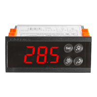
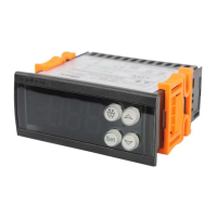
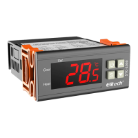
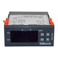
The ECS-2180neo is a microprocessor-based digital controller designed for managing refrigeration systems, specifically for medium to low-temperature applications. It features three relay outputs to control the compressor, fan, and defrost functions, which can be configured for either electric or hot gas defrost. The device comes with two NTC temperature probes, one for thermostatic control of the cabinet and another for evaporator defrost control.
The primary function of the ECS-2180neo is to regulate the cabinet temperature. This is achieved by monitoring the temperature using the indoor probe. When the temperature rises to the set point plus the differential, the compressor is activated. Conversely, when the temperature drops to the set point, the compressor switches off. A visual indicator on the display shows when the compressor relay is engaged, and it flashes during a delay to prevent short cycling, ensuring the longevity of the compressor. The controller also includes a compressor short cycle protection feature, adjustable from 0 to 90 minutes, to prevent excessive starting. In the event of a probe failure, the compressor can be configured to run for a timed period (0-60 minutes) to prevent product thawing or to cycle off for a timed period (0-60 minutes) to prevent freezing.
The controller supports various defrost modes, including electric heater or hot gas defrost. For medium-temperature applications, an "off-cycle" defrost can be utilized, where defrosting occurs when the compressor is off. Defrosting is interval-timed, with the interval adjustable by the user from 0 to 90 hours. The defrost period itself is also adjustable from 1 to 90 minutes. Defrost termination can be triggered by the defrost probe reaching a set temperature (0°C to 50°C) or by the expiration of the interval period. A visual indicator on the display signifies when defrost is active. After defrost, a drip time (0-60 minutes) is allowed for condensate to drain from the coil, preventing ice buildup. The defrost status display can be configured to show the cabinet temperature, "dEF," or the start-defrost cabinet temperature during defrost and drip time.
The fan control is highly configurable. It can be set to run simultaneously with the compressor, continuously, or to stop during defrost and drip time. A "fan time delay after defrost" feature allows for a delay before the fan restarts after defrost. The fan motor also incorporates a high-temperature stop point (adjustable from -50°C to 85°C) as a safety measure to prevent the circulation of warm air within the cabinet. In some configurations, the fan operation can be controlled by the defrost sensor.
The ECS-2180neo includes comprehensive alarm features to alert users to potential issues. It supports high and low-temperature alarms for the cabinet, with adjustable alarm ranges and delay times (0-60 minutes) before activation. There are also alarms for sensor failures (cabinet, evaporator, condenser), condenser high temperature, and copy card programming failures. The buzzer can be muted by pressing any key. The alarm relay can be configured to act as either a light output or an alarm output.
The device can integrate with a door switch to manage various functions. When the door is open, the fan can be closed, and the light can be turned on or off. It can also be configured to initiate defrost when the door is open, acting as a synchronous signal input for defrost. The buzzer can be set to respond when the door is open.
The controller allows for easy adjustment of various parameters. The set point for temperature can be changed by pressing the "SET" button for 3 seconds, then using the up and down arrows to adjust the value. An administrator menu, protected by a password (default 55), provides access to advanced settings. This menu allows adjustment of parameters such as hysteresis value, compressor start minimum interval, cabinet sensor calibration, temperature set limits, maximum standby time, refrigeration minimum running time, evaporator sensor selection, defrost cycle calculation, defrost cycle interval, maximum defrost time, drip time, time delay after defrost start, defrost type, fan running mode, fan initial start time delay, fan start time delay after defrost, fan working lowest/highest temp, compressor run/stop proportional time, buzzer alarm output switch, cabinet temperature lower/upper limit alarm values, over temperature alarm time delays, and over temperature alarm deviation.
The device features an LED display that shows the current temperature and various status indicators. Indicator lights clearly show the status of setting, refrigeration, defrost, fan, defrost dripping, and door switch. These visual cues provide immediate feedback on the system's operation.
The ECS-2180neo supports a copy card function, allowing users to upload and download parameter settings. This feature simplifies the configuration of multiple devices with identical settings, saving time and ensuring consistency.
The manual provides a problem solver section to assist with common issues. It suggests checking probe connections and cleaning terminals for E1 or E2 alarms (sensor failures). It notes that probes can be extended up to 100m but may require recalibration. For LA alarms (excessive temperature), it advises allowing the controller to cool down, relocating it, or improving ventilation. If relays fail, users should check the full load amperage of the output to ensure it is within the controller's ratings. If defrost does not start, checking the coil temperature is recommended, and if the fan does not start, checking the coil temperature is advised.
The device allows for calibration of both cabinet and evaporator sensors (adjustable from -10°C to 10°C) to correct for inaccuracies due to extended probes or interference.
A comprehensive list of alarm codes is provided, detailing the reason for each alarm, such as cabinet temperature sensor failure (E1), evaporator sensor failure (E2), condenser sensor failure (E3), condenser high temperature alarm (CH), cabinet high temperature alarm (rH), cabinet low temperature alarm (rL), copy card programming failure (Er), and inconsistent data between copy card and controller (EP). This helps in quickly diagnosing and addressing issues.
The manual emphasizes several safety precautions, including installation by qualified personnel, checking supply voltage, avoiding exposure to water or moisture, disconnecting electrical connections before maintenance, and using mains filters with inductive loads in industrial applications. In case of failure, returning the device to the supplier with a detailed report is recommended.
| operating temperature | -5 to 55°C |
|---|---|
| storage temperature | -10 to 65°C |
| temperature range | -40 to 90°C |
| power supply | 12/24 Volt DC |
|---|---|
| power consumption | < 10 watts |
| compressor output current | 17/7 Amp |
|---|---|
| fan output current | 10 Amp |
| defrost output current | 10 Amp |
| front panel dimensions | 34.5 (H) x 76mm (W) +/- 2mm |
|---|---|
| cut out dimensions | 30 (H) x 72mm (W) +/- 1mm |