Defrost type
System status
Electric defrost Reverse cycle defrost Free defrost
Cooling
Compressor is on Compressor is on Compressor is on
Electric heang is off Four-way valve closes. --
Defrost
Compressor is off Compressor is on Compressor is off
Electric heang is on Four-way valve opens. --
Dripping
Compressor is off Compressor is off Compressor is off
Electric heang is off Four-way valve opens. --
User Manual ECS-974neo Temperature Controller
ddL=2: displays the label “dEF” during defrosng, and unl the next me the Set-point value is reached.
6) Defrost type: dty = 0: electric defrost; dty = 1: reverse cycle defrost (hot gas); dty = 2: Free defrost (compressor hot).
7.3 Fan
If evaporator sensor is enabled (H42=y), fan runs per evaporator temperature. Fan runs when the temperature value read by evaporator
probe < FSt (Fan stop temperature) – FAd (Fan acvaon differenal). Fan stops when the temperature value read by evaporator probe
> FSt.
In cooling status: FCO=y (Fan acvated), fan runs only based on the value read by the evaporator probe. FCO=n(Fan off), fan runs only
based on the value read by the evaporator probe when compressor switches on for cooling.
In defrosng status: dFd=y(Defrost fan disable), fan runs only based on the value read by the evaporator probe.
dFd=n, fan stops during defrosng.
Fan is acvated when Fan delay me (Fdt) elapses aer a defrost operaon.
When evaporator sensor is faulty or disabled, fan does not run based on the value read by the evaporator probe. i.e. in cooling status:
FCO=y (Fan acvated), fan runs.
FCO=n(Fan off), fan runs when compressor switches on for cooling. Fan stops when compressor switches off.
In defrosng status: dFd=y(Defrost fan disable), fan runs during defrosng.
dFd==n, fan stops during defrosng.
Fan is acvated when Fan delay me (Fdt) elapses aer a defrost operaon.
7.4 Alarm
When cabinet sensor fails, E1 is displayed. When evaporator sensor fails, E2 is displayed.
High cabinet temperature alarm is triggered when cabinet temperature > SEt value + HAL (High Alarm differenal), and temperature
alarm delay elapses. AH1 is displayed. High cabinet temperature alarm is removed when cabinet temperature < SEt value + HAL.
Low cabinet temperature alarm is triggered when cabinet temperature < SEt value - LAL (Low Alarm differenal), and temperature alarm
delay elapses. AL1 is displayed. Low cabinet temperature alarm is removed when cabinet temperature > SEt value + LAL.
Note:Temperature alarm delay equals to PAO (Power-on Alarm Override) aer power on for the first me, dAO (defrost Alarm
Override) during defrosng and tAO (temperature Alarm Override) in other condions.
8. Fault code
Fault
Cabinet sensor fault
Evaporator sensor fault
High cabinet temperature alarm
Low cabinet temperature alarm
Copy card programming failure
The data in copy card disagrees with controller model, causing programming failure.
Reset to default (the second copy).
Display
E1
E2
AH1
AL1
Er
EP
rSt
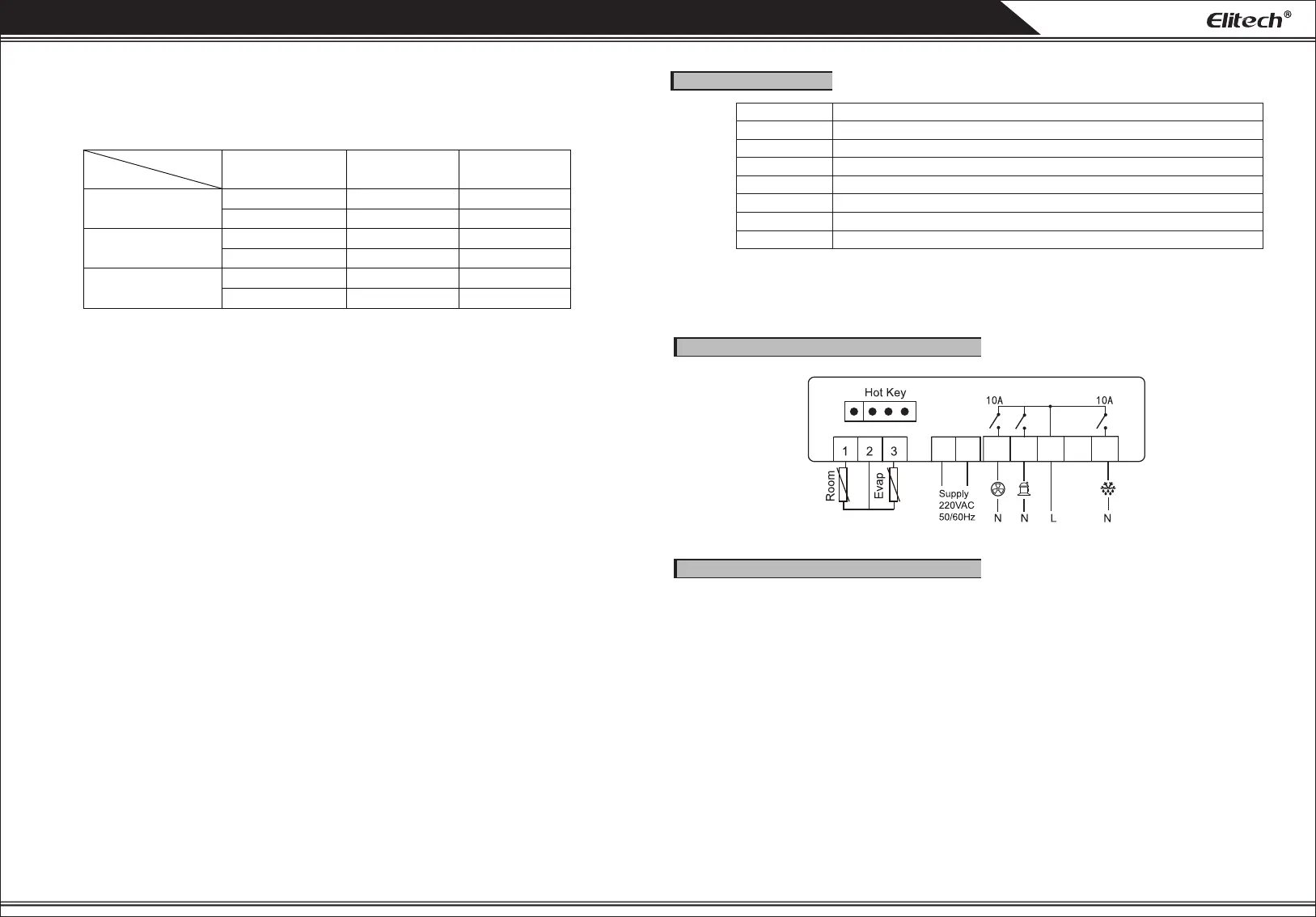
9. Wiring diagram:(Refer to actual products)
10. Safety precautions
1)Do disnguish the ports of sensor lead, power cord and relays. Please do not connect lines wrong. The relay cannot be overloaded.
2)Wiring requires disconnecon of power supply first.
★ Warning:
The controller is forbidden to be used in water or too humid environment, high temperature, strong electromagnec interference or
strong corrosion environment.
★ Noce:
1)The power voltage must be in accordance with the voltage labeled on the controller. Please ensure the stability of power voltage.
2)Suggest keeping suitable distance between sensor lead and power cord to avoid possible interference.
3)Remove the sensor by slightly plugging out its end downwards.
17(5)A
4 5 6 7 8 9 10
V1.0
 Loading...