EasyManua.ls Logo

Elitech STC-1000X User Manual

Elitech STC-1000X
2 pages
To Next Page IconTo Next Page
Page #1 background imageLoading...
Page #1 background image
STC-1000X Microcomputer Temperature Controller User Manual
Overview
STC-1000X temperature controller features cooling and heating modes with automatic
switch, temperature unit switch between Celsius and Fahrenheit, temperature control
by set-point and differential, temperature calibration, cooling output protection delay,
sensor fault alarm and other functions. The controller reserves an interface of RS-485
communication function for further connection to an Elitech IoT module which makes
remote control available.
Specifications
Power Supply
Measurement Range
Temperature Resolution
Temperature Accuracy
Total Power Consumption
Operating Ambient Temperature
Storage Temperature
Relative Humidity
Relay Contact Output Rating
Sensor
Waterproof Grade Of Front Panel
Panel Size
Mounting Size
Product Size
Sensor Cable Length
Based on: 220V±10%, 50/60Hz;
110V±10%, 50/60Hz; 24VAC/DC; 12VAC/DC;*
-50°C~120°C/-55°F~248°F
0.1°C
±1°C (-20°C~50°C)/±2°F, ±1.5°C/±3°F (others)
< 3W
0°C~60°C
-30°C~75°C
20%~85%RH (non-condensing)
Cooling/Heating: 10A/250VAC
NTC (10K/25°C, B value = 3435K)
IP65
80 x 35 mm
71 x 29 mm
80 x 35 x 66 mm
2m (probe length included)
Operation & Display Panel
ON/OFF Button
Down Button
Temperature Unit Indicator Set ButtonUp Button
Cooling Indicator
Button Lock Indicator
Heating Indicator
Network Indicator
ON/OFF Indicator
Setting Indicator
Button Instructions
Quick Start
1. Unlock the keyboard
Under normal operating status, the buttons will be locked after 10 seconds of
inactivity, and the button lock indicator will be on. Hold button for more
than 3 seconds to unlock the buttons and will be off.
2. View parameters
Under normal operating status, press and release button to display the temperature
set-point; press and release button to display the temperature differential set-point.
The controller will be back to normal display status after 2 seconds.
3. Set parameters
Under normal operating status, press and hold button for more than 3 seconds
to enter parameter setting mode. The indicator will be on and the first code F1
/
Press and release: Back to previous menuHold for 3 seconds: Turn ON/OFF; .
Press and release: Display temperature set-point and back to normal display after 2 seconds.
Press and release: Display temperature differential set-point and back to normal display after 2
seconds.
Hold for 3 seconds: Unlock the keyboard or enter parameter setting mode.
/
/
/
/
will be displayed in the panel. Press or button to scroll up or down menu items
and display the corresponding code. Press button to display the current parameter
set-point. Press or button again to increase or decrease the value and press
to back to parameter code display.
If you need to save the settings, please press and release button and back to normal
display status. If not, just keep the controller inactive for 10 seconds, it will be back to
temperature display status. If an error occurs during saving settings, the panel will
display Er and back to temperature display status in 3 seconds.
4. Operations
Under normal operating status, the panel displays currently measured temperature
and automatically recognizes and switches cooling and heating modes.
- If measured temperature  temperature set-point + temperature differential, and
compressor delay time  F3, the controller starts cooling mode and indicator is on.
- If measured temperature  temperature set-point, the controller stops cooling and
indicator is off.
- If measured temperature  temperature set-point - temperature differential, the
controller starts heating mode and indicator is on.
- If measured temperature  temperature set-point, the controller stops heating and
indicator is off.
5. ON/OFF
Hold the power button for more than 3 seconds to turn on/off the controller.
/
/
Menu
Code Function Setting Range Default Remark
F1
Temperature Set-point
-49~109°C/-56~228°F
10°C/50°F
3°C/37°F
0°C/0°F
3
0
1 Reserved
1~10°C/33~50°F
0~10 min
-10°C~10°C/-10~10°F
0: °C 1: °F
1~127
Temperature Differential
Compressor Start Delay
Temperature Calibration
Temperature Unit
Communication Address
F2
F3
F4
F5
F6
Fault & Alarm
When the temperature sensor is short circuit or open circuit, the controller will start
fault alarm mode and turn off all the outputs, the buzzer will beep and the panel will
display EE. Press any button to mute the buzzer.
The controller will return to normal operating mode after the fault is removed.
Safety Precautions
Important!
1. Distinguish the sensor lead, power cord and output relay interface. Do not connect
wrong or overload the relay.
2. Cut off power supply before wiring.
Warning!
Do not use the controller in water or too humid environment, or environments at high
temperature, with strong electromagnetic interference or strong corrosion.
Wiring Diagram
Caution!
1. The power voltage must be in accordance with the voltage labeled on the controller.
Please ensure the stability of power voltage.
2. Separate as much as possible the sensor lead from power cables to avoid possible
electromagnetic disturbance.
L
N
SensorPower
Heating Cooling
* The details should be refer to the wiring diagram of actual device.
Question and Answer IconNeed help?

Do you have a question about the Elitech STC-1000X and is the answer not in the manual?

Elitech STC-1000X Specifications

General IconGeneral
Sensor TypeNTC Sensor
Resolution0.1 °C
MountingPanel Mount
Temperature Range-50°C to 99.9°C (-58°F to 211.8°F)
Control TypeOn/Off
Power SupplyAC 220V
Relay Output10A
HysteresisAdjustable
Accuracy±1°C (±1.8°F)

Summary

Overview

Specifications

Power Supply

Power supply requirements and available voltage options for the controller.

Measurement Range

The range of temperatures the controller can measure.

Temperature Resolution

The smallest temperature increment the controller can detect.

Temperature Accuracy

The precision of the controller's temperature readings.

Total Power Consumption

The maximum electrical power consumed by the controller.

Operating Ambient Temperature

The suitable range of ambient temperatures for controller operation.

Storage Temperature

The recommended temperature range for storing the controller.

Relative Humidity

The acceptable range of non-condensing humidity for operation.

Relay Contact Output Rating

The electrical specifications for the controller's output relays.

Sensor Type

The type of temperature sensor utilized by the controller.

Waterproof Grade Of Front Panel

The level of protection the front panel offers against water.

Panel Size

The physical dimensions of the controller's front panel.

Mounting Size

The cutout dimensions required for installing the controller.

Product Size

The overall physical dimensions of the controller unit.

Sensor Cable Length

The length of the included temperature sensor cable.

Operation & Display Panel Elements

Temperature Unit Indicator

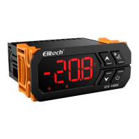
Indicates the currently selected temperature unit (°C or °F).

Cooling Indicator

Shows when the cooling mode is active.

Heating Indicator

Shows when the heating mode is active.

ON/OFF Indicator

Indicates the power status of the controller.

Button Lock Indicator

Shows when the control buttons are locked.

Network Indicator

Indicates the status of network connectivity.

Up Button / Set Button

Used for navigating menus and adjusting settings.

ON/OFF Button

Used to turn the controller on or off.

Setting Indicator

Indicates when the controller is in parameter setting mode.

Down Button

Used for navigating menus and adjusting settings.

Button Instructions

ON/OFF and Menu Navigation

Instructions for turning the controller on/off and navigating menus.

Viewing Temperature Set-point

How to display the current temperature set-point.

Viewing Temperature Differential

How to display the current temperature differential.

Keyboard Unlock / Parameter Setting

How to unlock the keyboard or enter parameter setting mode.

Quick Start Guide

Unlock Keyboard

Procedure to unlock the controller's buttons after inactivity.

View Parameters

How to view the temperature set-point and differential.

Set Parameters

Steps to enter and modify parameter settings.

Parameter Menu

F1 Temperature Set-point

Setting the target temperature for heating or cooling.

F2 Temperature Differential

Setting the temperature difference for switching modes.

F3 Compressor Start Delay

Setting the delay before the compressor starts.

F4 Temperature Calibration

Adjusting the temperature reading for accuracy.

F5 Temperature Unit

Selecting the display unit for temperature (°C or °F).

F6 Communication Address

Setting the controller's address for communication.

Fault & Alarm Conditions

Safety Precautions

Wiring and Relay Interface

Important notes on distinguishing sensor leads, power cords, and relays.

Power Supply Cutoff

Requirement to cut off power supply before performing any wiring.

Warning

Wiring Diagram

Cautionary Notes

Power Voltage Stability

Ensuring the power voltage matches the controller's label and is stable.

Cable Separation

Separating sensor leads from power cables to prevent interference.

Controller Operations

Normal Operation Mode

Describes automatic cooling/heating switching based on temperature.

ON/OFF Function

How to turn the controller on or off using the power button.

Menu Navigation and Parameter Setting

Entering Parameter Setting Mode

How to enter the parameter modification mode using buttons.

Scrolling Through Menu Items

Using buttons to navigate and display menu codes and parameters.

Adjusting Parameter Values

Using buttons to increase or decrease parameter values.

Saving Settings

How to save modified settings or how they are saved automatically.

Main Functions

Function and Technical Parameters

Power Supply Options

Details on the available power supply options for the controller.

Measurement Range

The temperature measuring range of the device.

Temperature Resolution

The smallest unit of temperature measurement.

Temperature Accuracy

The precision of temperature readings.

Total Power Consumption

The maximum power consumed by the controller.

Operating Environment Temperature

The temperature range for optimal controller operation.

Storage Temperature

Recommended temperature range for storing the unit.

Relative Humidity

The non-condensing humidity range for operation.

Relay Output Capacity

The electrical rating of the relay outputs.

Sensor Specification

Details on the NTC sensor type and specifications.

Front Panel Protection Grade

The level of water protection for the front panel.

Front Panel Size

The dimensions of the controller's front panel.

Mounting Hole Size

The required cutout dimensions for installation.

Overall Size

The complete physical dimensions of the controller.

Sensor Cable Length

The length of the sensor cable provided.

System Faults and Alarms

Sensor Fault Alarm

Behavior and indication during sensor short or open circuit faults.

Safety Regulations

Wiring Distinction and Overload

Distinguish sensor, power, and output interfaces to prevent errors.

Power Disconnection for Wiring

Always disconnect power before making wiring changes.

Environmental Warnings

Precautions

Power Voltage Matching

Ensure power voltage aligns with controller labeling for stability.

Cable Interference Prevention

Separate sensor leads from power cables to minimize electromagnetic interference.

Wiring Diagram

Button Operation Guide

Control Function ON/OFF

How to turn the control function on or off.

Parameter Viewing

How to view temperature set-point and differential.

Quick Operation Guide

Button Unlocking

How to unlock buttons after the controller locks them.

Parameter Viewing

How to view temperature set-point and differential values.

Related product manuals