Haswill Electronics
2 / 2
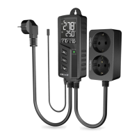
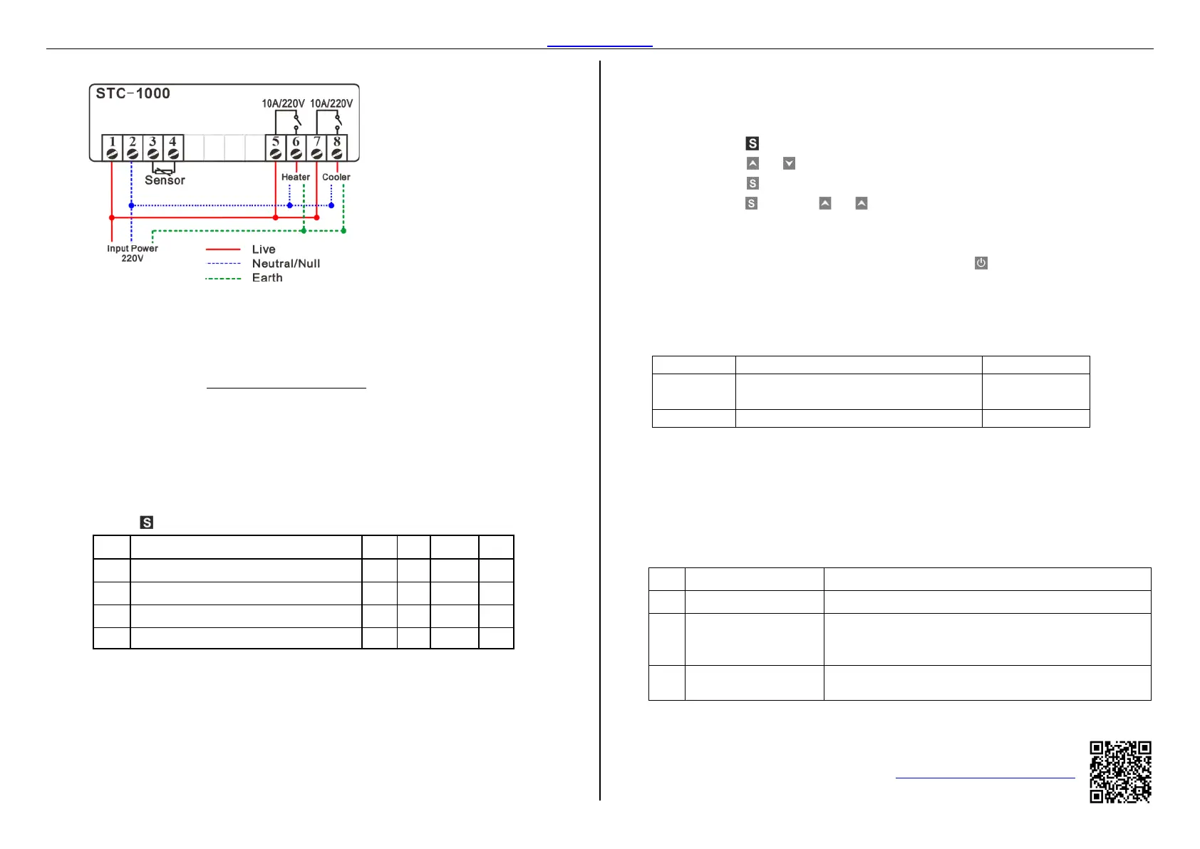
4.4. Wiring Diagram
A. Need not to distinguish + or - when wiring the NTC sensor's cable or the Input power.
Wiring the 5 to the live wire and terminal 6 to a heater, or the opposite.
Wiring the 7 to the live wire and terminal 8 to a refrigerator, or opposite.
The heating and cooling mode will switch automatically.
B. The input voltage must be within the voltage value marked in the diagram ±10% value.
C. Load Wattage ≤
Load Voltage ∗ Max Current of Relay
Power Factor
The factor for Inductive Load like compressor, motor, heating pump, usually be 5~8;
The factor for Resistive Load like Electric heating rod, Electric blanket usually is
1.5~2.
The factor for Incandescent lamps is usually nearly 15.
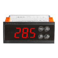
5. Configurations
5.1. Code and Function Menu
Hold the button for 3s to enter the menu list .
Code
Function Min Max
Default
Unit
Temperature Setpoint -50.0
99.9
10.0
°C
Temperature Hysteresis / Return Difference
0.3
10.0
0.5
°C
Protection Delay Time for Refrigerator 1
10
3
Min
Temperature Calibration -10.0
10.0
0
Hour
F1: Temperature Setpoint
It is the room temperature value users wish to keep around.
F2: Temperature Hysteresis / Return Difference Value
A. Switch to heating mode once found
Measured Temperature ≤ Temp Set-point – Return Difference
B. Switch to Refrigeration mode once found
Measured Temperature ≥ Temp Set-point + Return Difference
But the compressor will not start up until the compressor's delay time is over.
F3: Compressor Delay Time: The purpose of this value is to protect the compressor.
F4: Temperature Calibration
F4 = Real Temperature – Measured Temperature
5.2. How to Set Parameters?
Hold the for 3s to enter the menu list; the display shows the code
F1
Press the or to select the code you want to update;
3:
the to check the current value.
Hold the and press or key to change the value;
4:
keys to back to function menu list.
Repeat operation from Step 2 / 3 / 4 to adjust other parameters;
configuring all values, remember to press the for saving data, and back to
, the display shows the room sensor temperature.
he modified value will be discarded and back to normal status if without operation
5.3. When Will is the Load Works/Stops?
F1
F2
and
The instant period passed the delay time (
F3
F1
Room Temp: Measured temperature value by the controller's sensor.
F2: Return difference Hysteresis.
The instant period is counts from load stops last moment to the instant time;
In other words, the time should be later than the compressor's last stops moment + delay
time.
6. Error & Solution
When an alarm occurred, the buzzer scream "di-di-di," press any key to stop screaming; but the
error code on display will not disappear until all the failures are resolved
Code
Reason Troubleshooting
E1
Press/key to restoring the default data or get factory reset.
EE
Ensure the sensor was installed firmly or replace a new
sensor, display back to normal in 10 seconds once the
HH
Check the room temperature and all loads, then stop the loads
from working manually if necessary.
Haswill Electronics
https://www.thermo-hygro.com
Copyright Haswill-Haswell All Rights Reserved
 Loading...