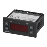
IC 912 2/4
ALARMS
Label Alarm
E1 Probe 1(control)
faulty
Resolving problems
• check the probe wiring
• replace the probe
Effects
“E1” label appears on display;
Controller enabled as indicated by the On1 and
OF1 parameters if programmed for the Duty Cycle
Cause
• measuring of values outside the nominal reading
range
• control probe faulty/shorted/open probe
HC1
PAR.
RANGE
DEFAULT
M.U.
H/C
H/C*
Flag
dF1
0...30.0 1
°C/°F
HS1
LS1...HdL
*
°C/°F
LS1
LdL...HS1 *
°C/°F
dn1
0...250 1
sec
do1
Controller - rE1 label
PAR.
RANGE
DEFAULT
M.U.
Display - dIS label
0...250 0
min
di1
0...250 0
min
dE1
0...250 0
sec
On1
0...250
0
min
OF1
0...250
1
min
LOC
n/y
n
flag
PA1
0
num
Configuration- CnF label
H00
(!)
IC 912 V-I 420/020/010/05/01
IC 912 Pt100-Tc(1) Pt1/JtC/HtC
*
*
num
num
H03***
*
num
IC 912 V-I (ndt=n) -99...100
(ndt=y) -99.0...100.0
(ndt=int) -990...1000
H04***
*
num
H10
0...250 0
min
PARAMETER TABLE
SP1
LS1...HS1
0.0
°C/°F
0...250
ndt
n
num
IC 912 V-I n/y/int
IC 912 Pt100-Tc n/y
flag
CA1
dro**
°C
flag
IC 912 Pt100-Tc °C/°F
LdL***
num
IC 912 V-I -99.9...HdL
0*
HdL***
num
IC 912 V-I LdL...100
100/100.0/1000*
IC 912 V-I (ndt=n) -99...100
(ndt=y) -99.0...100.0
(ndt=int) -990...1000
rEL
//
/
tAb
///
Fpr
UL
//
/
dL
//
/
Fr (2)
//
/
NOTE:
(1) The Pt100 model only works with the Pt100 input (3 wires) whereas
Tcj/TcK models, on the basis of this parameter, can work with the Tc input
and the Pt100 input.
(2) If the Fr command is used, the data entered in the card will be perma-
nently lost. This operation cannot be undone. After the operation with the
Copy Card, the controller must be switched off and then switched back on
WARNING(!) If one or more parameters marked with (!) are modified, the
controller must be switched off after the modification and then switched
back on
* The default value depends on the model
** The dro parameter is not present in IC 912 Pt100-Tc models
*** The LdL, HdL, H03 and H04 parameters are only present in the
IC 912 V-I models
CONTROLLER (folder with “rE1” label)
HC1 If set to H, the controller operates in heating mode. If set to C,
the controller operates in cooling mode.
dF1 Relay 1 intervention differential. The load will stop when Set
point is reached (as indicated by the control probe) and will
restart at a temperature equal to Set point plus (or minus
depending on HC1) the value of the differential. See ON-OFF
control diagram
HS1 Maximum value for set point.
LS1 Minimum value for set point.
CONTROLLER PROTECTIONS (folders with “rE1” label)
dn1 Start-up delay. The specified time must elapse between the
controller relay start-up request and actual start-up.
do1 Delay after shut-down. The specified time must elapse between
shut-down of the controller 1 relay and a subsequent start-up.
di1 Delay between start-ups. Between two subsequent start-ups of
the controller, the specified time must elapse.
dE1 Shut-down delay. The specified time must elapse between the
controller relay shut-down request and actual shut-down
.
NOTE: for parameters dn1, do1, di1, dE1 0= not active
On1 Controller start-up time if probe is faulty. If set to “1” with Of1
at “0” the controller is always on whereas if
Of1>0 it operates in duty cycle mode.
OF1 Controller shut-down time if probe is faulty. If set to “1” with
On1 at “0” the controller is always off whereas if On1>0 it
operates in duty cycle mode.
DISPLAY (folder with “diS” label)
LOC Keyboard locked (set point and buttons). However, you can still
access the parameter programming menu and modify
parameters including the status of this parameter to allow
keyboard unlocking. y = yes; n = no.
PA1 Password 1. When enabled (value is not 0) it represents the
access key to level 1 parameters.
ndt number display type.Display with decimal point.
y = yes, range = -99...100
n = no, range = -99,9...100.0
int=integer, range = -990...1000
CA1 Calibration 1. Positive or negative temperature value that is
added to the value read by control probe (probe 1) before
being displayed or used for control.
dro Select °C or °F to display temperature read by probe.
N. B.: switching from °C to °F DOES NOT modify set
points, differentials, etc. (for example set point=10°C
becomes 10°F).
LdL Minimum value the instrument is able to display.
HdL Maximum value the instrument is able to display.
CONFIGURATION (folder with “CnF” label)
H00 Selection of probe type.:
IC 912 V-I: 420=4...20mA, 020=0...20mA, 010=0...10V, 05=0...5V,
01=0...1V
IC 912 TcJ: Pt1=Pt100, JtC=Tcj, HtC=Tck
H03 Minimum value of current input
H04 Maximum value of current input
H10 Output delay from power-on Attention! If = 0 is not active; if ≠
0 the output will not be activated before this time has expired
rEL Device version. Read only parameter.
tAb Reserved. Read only parameter.
COPY CARD (folder with “Fpr” label)
UL UpLoad: transfer of programming parameters from instrument
to
Copy Card.
dL downLoad: transfer of programming parameters from Copy
Card to instrument.
Fr Format. Cancelling all data entered in the copy card.
N.B.: If “Fr” parameter (copy card formatting) is used, the
data entered in the card will be permanently lost. This
operation cannot be undone. After the operation with the
Copy Card, the controller must be switched off and then
switched back on
DESCRIPTION OF PARAMETERS
-30.0...30.0 0.0
num

 Loading...